Fixing method and fixing structure for fixing a coil insulator, stator using the same and rotating electrical machine using the same

a technology of fixing structure and coil insulator, which is applied in the direction of dynamo-electric machines, electrical devices, windings, etc., can solve the problems of projections being caught by teeth, and achieve the effect of stable fixing condition and looseness

Active Publication Date: 2016-07-21
TOYOTA JIDOSHA KK
View PDF3 Cites 6 Cited by
  • Summary
  • Abstract
  • Description
  • Claims
  • Application Information

AI Technical Summary

Benefits of technology

[0007]The present invention provides a fixing method and a fixing structure for fixing a coil insulator to a stator, which can prevent a fixing projec

Problems solved by technology

Thus, when the insulators are installed to the divided stator core secti

Method used


Image

  • Fixing method and fixing structure for fixing a coil insulator, stator using the same and rotating electrical machine using the same
  • Fixing method and fixing structure for fixing a coil insulator, stator using the same and rotating electrical machine using the same
  • Fixing method and fixing structure for fixing a coil insulator, stator using the same and rotating electrical machine using the same

Examples


Embodiment Construction

[0038]Hereinafter, embodiments of the present invention will be described in detail with reference to the accompanying drawings. In this description, a specific shape, material, numeral, direction and the like are exemplifications which facilitate understanding of the present invention and may be changed appropriately depending on a purpose, object, specification and the like. Further, if a plurality of embodiments or modifications are included in the description below, it is expected from the beginning that some characterizing portions thereof are combined appropriately for use.

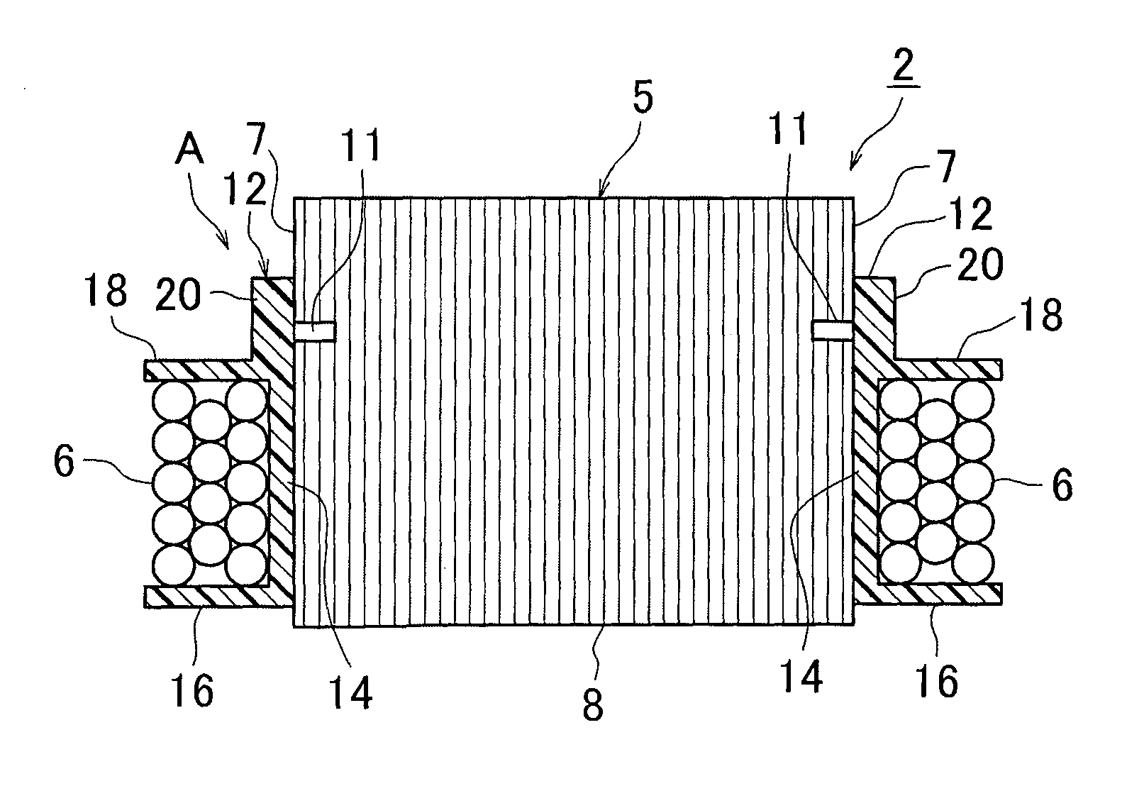
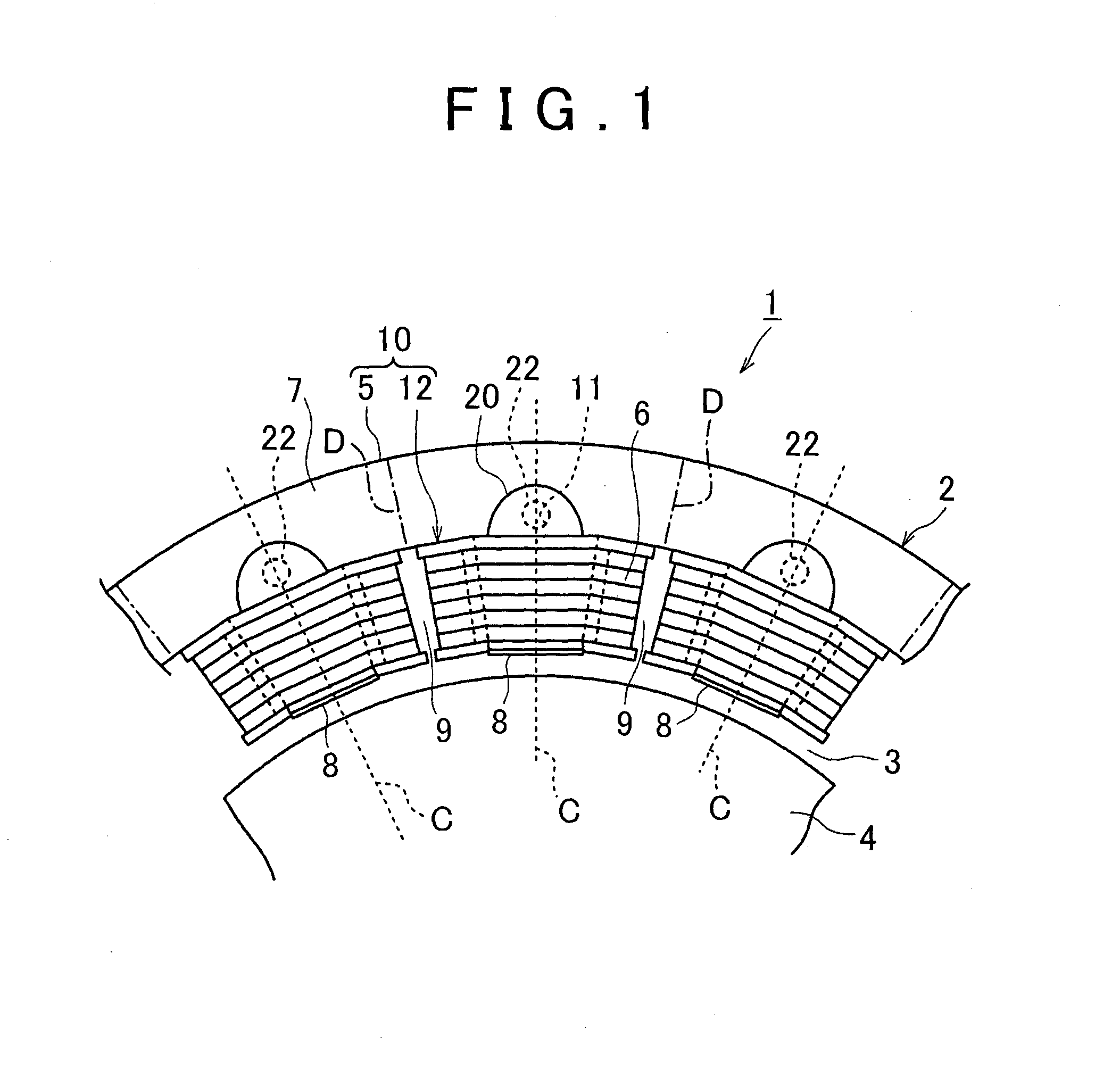
[0039]FIG. 1 is a partial end face view taken in the axial direction of a rotating electrical machine 1 including a coil insulator fixing structure 10 according to an embodiment of the present invention. The rotating electrical machine 1 includes a substantially cylindrical stator 2 and a rotor 4 provided inside in the radial direction of the stator 2 across a gap 3. The rotor 4 is supported rotatably in a c...


PUM


Abstract

A fixing method for fixing a coil insulator which is provided between a stator core 5 including a back yoke 7 and a plurality of teeth 8 projecting in the radial direction from the back yoke 7, and a coil 6 wound around the stator core 5, to the stator core 5, includes preparing the stator core 5 in which a fixing hole 11 is formed corresponding to a respective one of the teeth 8, on an end face in the axial direction of the back yoke 7, and preparing a plurality of coil insulators 12 which include each a main body 14 composed of a heat-softenable insulating material and arranged on the circumference of a respective, one of the teeth 8, and a fixing portion 20 which is projected in the radial direction from the main body 14 and covers the fixing hole 11. Each coil insulator 12 is arranged on the circumference of a respective one of the teeth 8 by fitting thereto. By softening the fixing portion 20 by heating to bring part of the insulating material into the fixing hole 11 and then hardening the fixing portion 20, a projection 22 for fixing the coil insulator 12 to the stator core 5 is formed.

Description

BACKGROUND OF THE INVENTION[0001]1. Field of the Invention[0002]The present invention relates to a fixing method and a fixing structure for fixing a coil insulator which is provided between a stator core and a coil wound around the stator core, to the stator core in a rotating electrical machine.[0003]2. Description of Related Art[0004]Conventionally, there has been known a rotating electrical machine which includes a stator formed by winding a coil around teeth of the same stator and a rotor provided rotatably with respect to the stator across a gap. In such a rotating electrical machine, the coil wound around the stator is electrically insulated by interposing coil insulator composed of insulating material such as resin between the coil and the stator core, for example.[0005]As a relevant related art document, Japanese Patent Application Publication No 2012-95492 (JP 2012-95492 A), for example, has described that in a stator of an electric motor, a coil insulator is arranged at ea...

Claims


Application Information

Patent Timeline
IPC IPC(8): H02K15/10H02K3/52H02K3/34
CPCH02K15/10H02K3/521H02K3/345H02K3/32H02K3/46H02K3/522H02K15/12H02K2203/12
Inventor HATTORI, HIROYUKI
Owner TOYOTA JIDOSHA KK
Why Eureka
Try Eureka