Mirror

a technology of mirrors and mirror bodies, applied in the field of mirrors, to achieve the effect of suppressing the outer peripheral portion of the mirror body, reducing the heating density of the heating section, and reducing the stress

Active Publication Date: 2016-07-28
KK TOKAI RIKA DENKI SEISAKUSHO +1
View PDF2 Cites 0 Cited by
  • Summary
  • Abstract
  • Description
  • Claims
  • Application Information

AI Technical Summary

Benefits of technology

[0018]In the heated region of the mirror body, the spacing of the pair of electrodes is changed so as to change the amount of heat generated by the heat generation body. The heating density of the heating section can accordingly be easily changed.
[0019]In the mirror of the fourth aspect, in the heated region of the mirror body, the heating density of the heating section gradually decreases on progression from the central side of the mirror body toward the outer peripheral side of the mirror body. Accordingly, the temperature of the outer peripheral portion of the mirror body can be suppressed from rising suddenly on progression from the outer peripheral side toward the central side of the mirror body when the heating section has heated the heated region of the mirror body, thereby enabling stress arising in the outer peripheral portion of the mirror body to be effectively suppressed.

Problems solved by technology

Even when the heating section heats the heated region of the mirror body, heat escapes through outer peripheral end faces of the mirror body at an outer peripheral edge portion of the mirror body, such that the temperature does not readily rise.

Method used


Image

  • Mirror
  • Mirror
  • Mirror

Examples


first exemplary embodiment

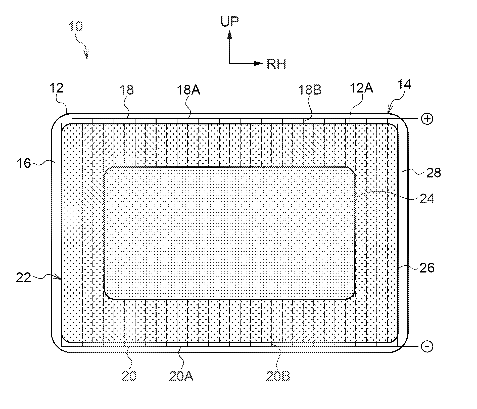
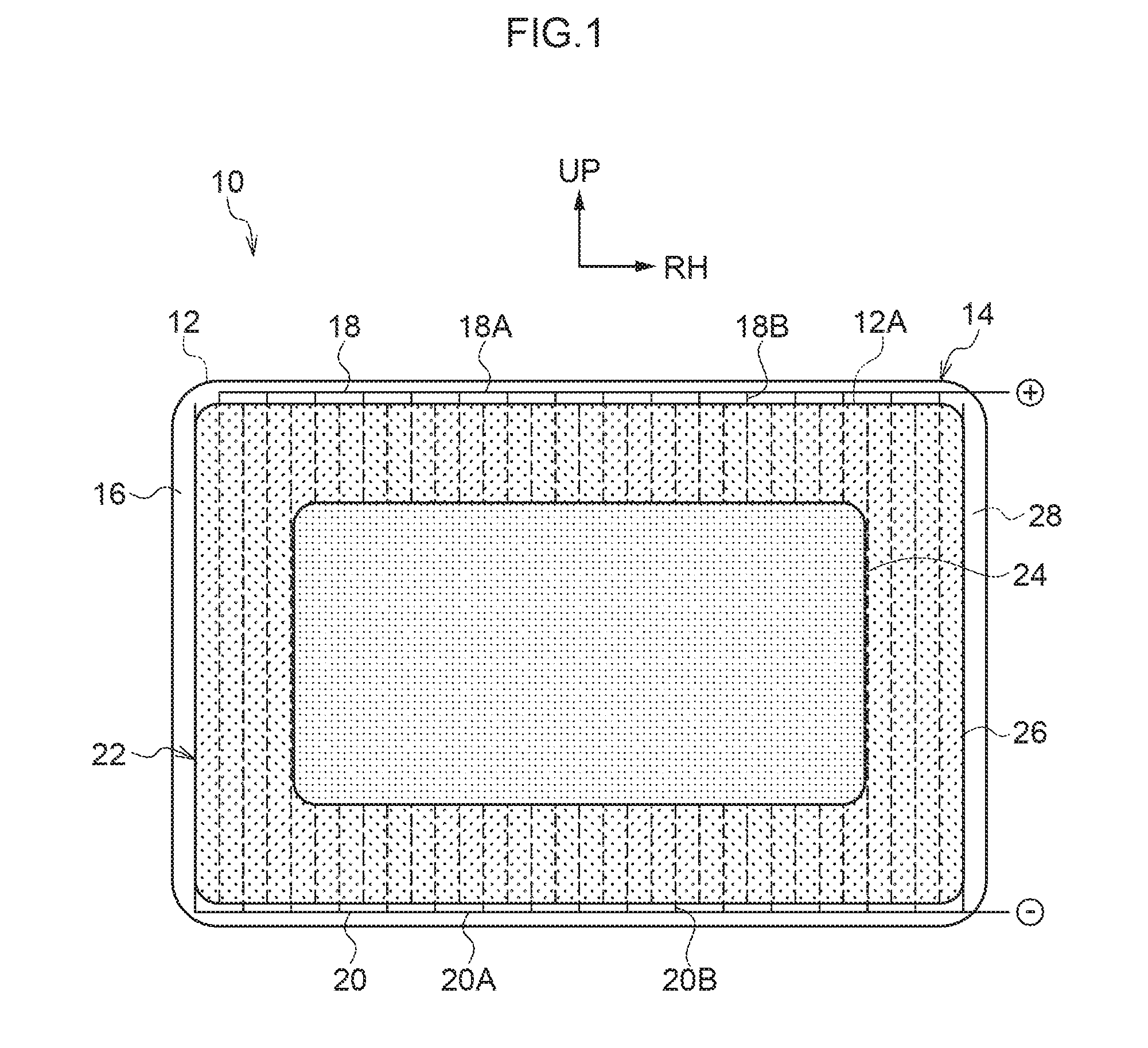
[0024]FIG. 1 is a face-on view illustrating a vehicle mirror 10, serving as a mirror according to a first exemplary embodiment of the present invention, as viewed from the mirror-viewing side (front side of the vehicle mirror 10). In the drawings, the arrow UP indicates upwards, and the arrow RH indicates the right.

[0025]The vehicle mirror 10 according to the present exemplary embodiment is provided at a vehicle, and for example, the vehicle mirror 10 is installed to a door (in particular, a side door), and is disposed at the exterior of the vehicle.

[0026]As illustrated in FIG. 1, the vehicle mirror 10 includes a rectangular plate shaped mirror body 12. A mirror-viewing side of the mirror body 12 is provided with a rectangular plate shaped glass plate, made from glass, as a substrate (base plate). The glass plate is transparent, and is capable of transmitting light. The entire back face of the glass plate is provided with a rectangular layer shaped reflective layer. The reflective l...

second exemplary embodiment

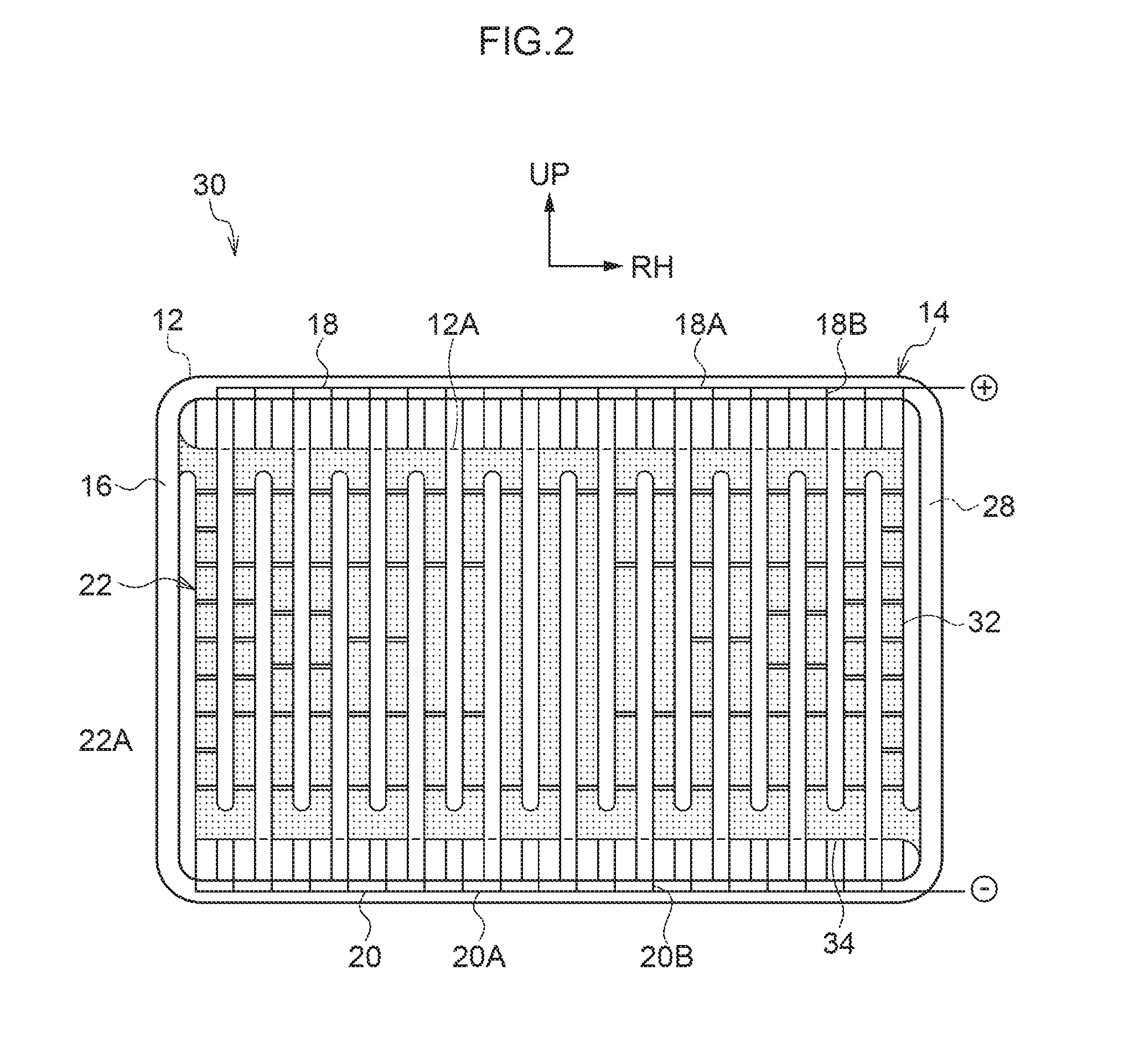
[0046]FIG. 2 is a face-on view illustrating a vehicle mirror 30, serving as a mirror according to a second exemplary embodiment of the present invention, as viewed from the mirror-viewing side.

[0047]The vehicle mirror 30 according to the present exemplary embodiment has substantially the same configuration as the first exemplary embodiment; however differs in the following respects.

[0048]As illustrated in FIG. 2, in the vehicle mirror 30 according to the present exemplary embodiment, the heat generating body 22 of the heater 14 is configured with a substantially wave shape as viewed face-on. The heat generating body 22 is provided with plural main body portions 32, and the plural main body portions 32 each extend in the up-down direction, and are disposed at uniform spacings (intervals) therebetween along the left-right direction. The heat generating body 22 is provided with plural coupling portions 34, and the coupling portions 34 couple together upper end portions or lower end por...


PUM


Abstract

In a vehicle mirror, a heat generating body of a heater generates heat so as to heat a mirror body. A central side portion and an outer peripheral side portion of the heat generating body configure a thick portion and a thin portion, and the thin portion generates a smaller amount of heat than the thick portion, such that a heating density of the mirror body by the heat generating body is lower on an outer peripheral side portion of the mirror body than at a central side portion of the mirror body. Accordingly, the temperature of an outer peripheral portion of the mirror body can be suppressed from rising suddenly on progression from the outer peripheral side toward the central side of the mirror body, thereby enabling stress arising in the outer peripheral portion of the mirror body to be suppressed.

Description

CROSS-REFERENCE TO RELATED APPLICATION[0001]This application claims priority under 35 USC 119 from Japanese Patent Application No. 2015-012417 filed Jan. 26, 2015, the disclosure of which is incorporated by reference herein.BACKGROUND[0002]1. Field of the Invention[0003]The present invention relates to a mirror in which a mirror body is heated by a heating section.[0004]2. Related Art[0005]In a heater-mirror described in Japanese Patent Application Laid-Open (JP-A) No. 2006-202675, a resistance heating element is disposed on a back face of a front surface mirror, and the resistance heating element generates heat to heat the front surface mirror.[0006]In such heated mirrors, it is desirable to be able to suppress stress from arising at an outer peripheral portion of the front surface mirror.SUMMARY[0007]In consideration of the above circumstances, a mirror capable of suppressing stress from arising at an outer peripheral portion of a mirror body is obtained.[0008]A mirror of a first ...

Claims


Application Information

Patent Timeline
Patent Type & Authority Applications(United States)
IPC IPC(8): B60R1/06G02B27/00
CPCG02B27/0006B60R1/0602B60R1/06H05B3/03H05B3/84H05B2203/02
Inventor AOKI, MASAKAZUKAJI, MASASHI
Owner KK TOKAI RIKA DENKI SEISAKUSHO
Why Eureka
Try Eureka