Display module

a technology of display modules and modules, applied in the field of display modules, can solve problems such as electrical connection failure between flexible wiring substrates, and achieve the effect of avoiding mutual interference between the first and second flexible wiring substrates

Active Publication Date: 2016-07-28
JAPAN DISPLAY INC
View PDF5 Cites 5 Cited by
  • Summary
  • Abstract
  • Description
  • Claims
  • Application Information

AI Technical Summary

Benefits of technology

[0007]In view of the above problem, it is an object of the present invention to avoid mutual interference between first and second flexible wiring substrates.
[0008]A display module according to an aspect of the present invention has a first circuit substrate, a second circuit substrate, a first flexible wiring substrate, and a second flexible wiring substrate. The first and second circuit substrates are flexible. The first circuit substrate has a display area provided with an image display function and has a first peripheral area outside the display area. The second circuit substrate has an additional function area provided with a function added to the image display function and has a second peripheral area outside the additional function area. The second circuit substrate partially overlaps with the first circuit substrate. The first flexible wiring substrate is joined to a first edge of the first peripheral area so as to be electrically coupled to the first circuit substrate. The second flexible wiring substrate is joined to a second edge of the second peripheral area so as to be electrically coupled to the second circuit substrate. The first and second circuit substrates are disposed so that the display area and the additional function area are superposed and so that the first and second edges are offset from each other. The first and second flexible wiring substrates are disposed so as not to overlap with each other. The first circuit substrate has a first curved portion in the first peripheral area. The second circuit substrate has a second curved portion in the second peripheral area. The first and second flexible wiring substrates each extend toward the opposite side of the first circuit substrate from the second circuit substrate. In this display module, the first and second flexible wiring substrates do not overlap with each other. Thus, mutual interference between the first and second flexible wiring substrates is avoided.

Problems solved by technology

If one of the flexible wiring substrates, which are joined to the corresponding edges of the flexible wiring substrates disposed on top of each other, has a projection on its surface, the projection may interfere with the other flexible wiring substrate and cause an electrical connection failure between the flexible wiring substrates.

Method used


Image

  • Display module
  • Display module
  • Display module

Examples


Embodiment Construction

[0021]The following describes embodiments of the present invention with reference to the accompanying drawings.

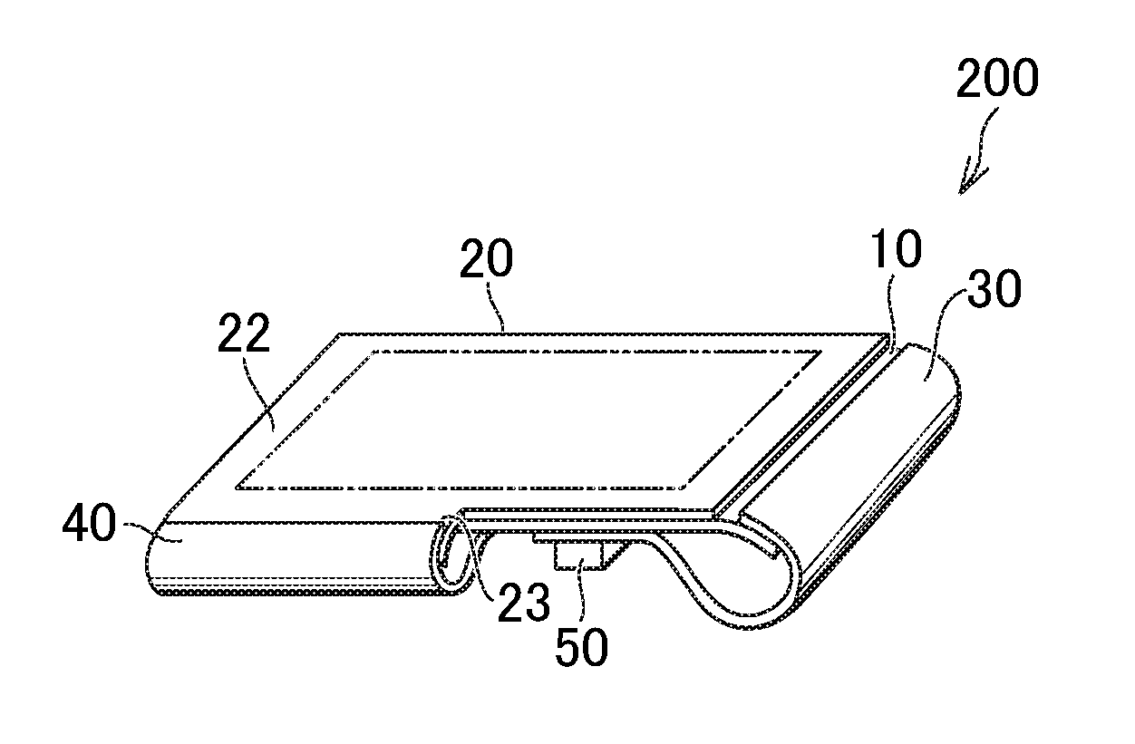
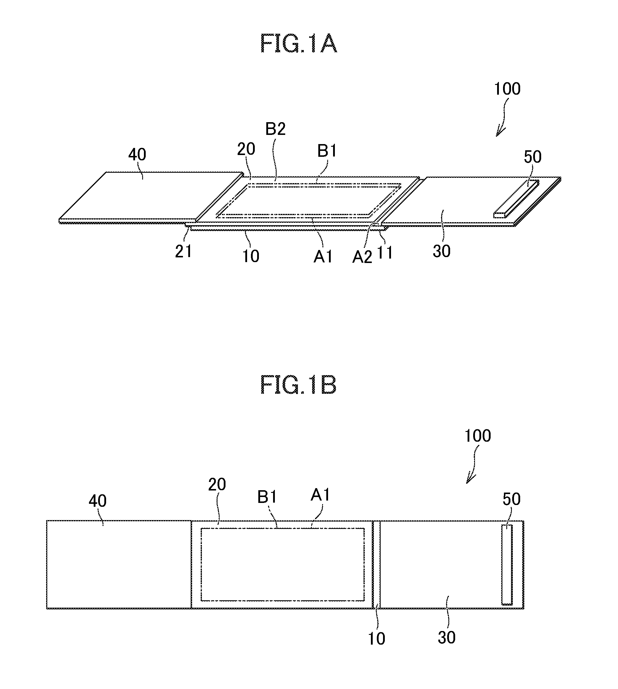
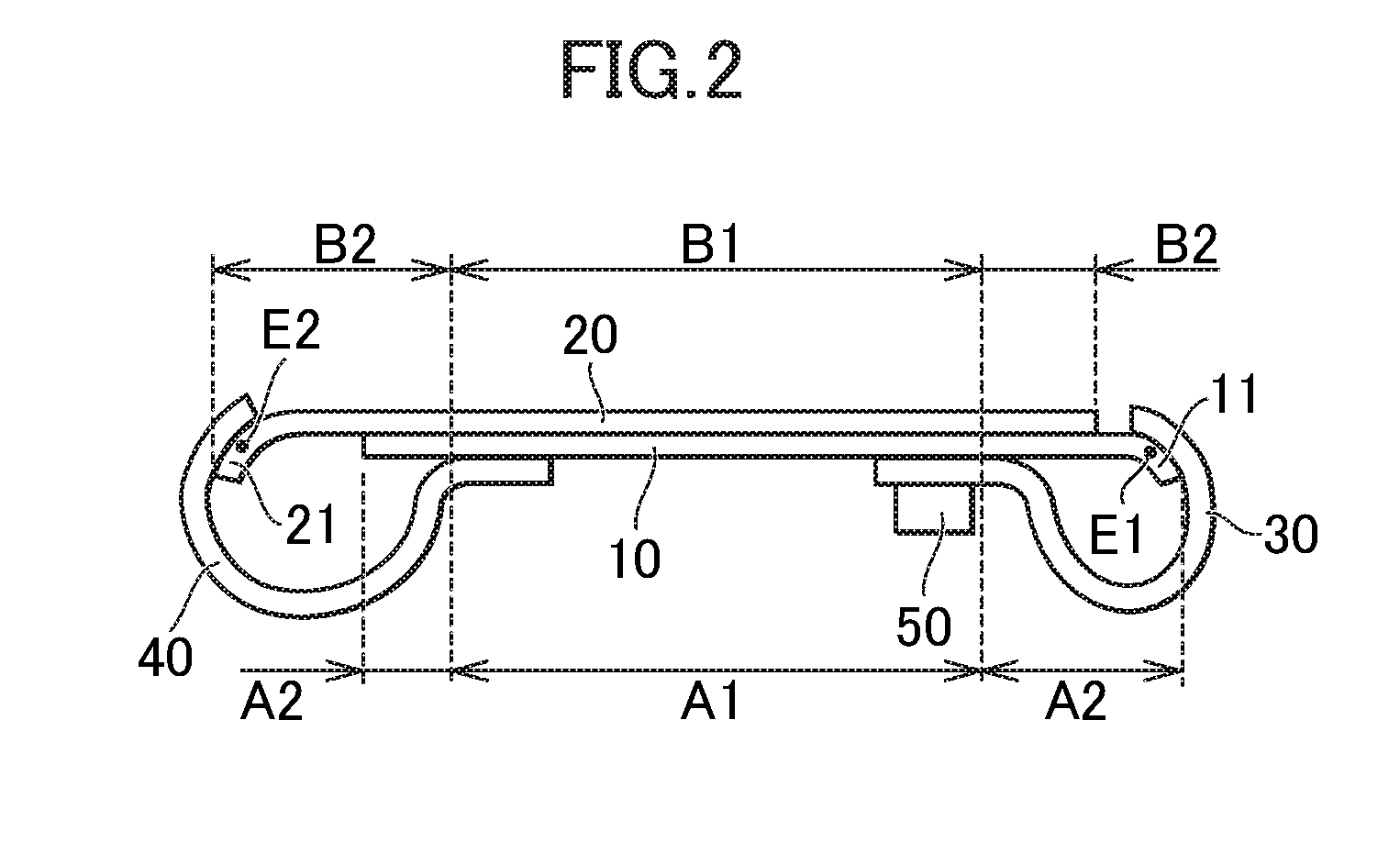
[0022]FIG. 1A is an external perspective view of a developed display module according to a first embodiment. FIG. 1B is a plan view of the developed display module according to the first embodiment. FIG. 2 is a side view of the display module according to the first embodiment. FIG. 3A is an external perspective view of the display module according to the first embodiment. FIG. 3B is a plan view of the display module according to the first embodiment, when viewed from the front surface side of its display area. FIG. 3C is a plan view of the display module according to the first embodiment, when viewed from the back surface side of the display area. An image display panel 10 has a display area. The front surface of the display area is the surface facing a touch screen 20 and the back surface of the display area is the opposite side of the image display panel 10 from the touch...


PUM


Abstract

A display module includes an image display panel, a touch screen, a first FPC substrate, and a second FPC substrate. The first and second FPC substrates are disposed so as not to overlap with each other. The image display panel has a first curved portion in its first peripheral area. The touch screen has a second curved portion in its second peripheral area. The first and second FPC substrates each extend toward the opposite side of the image display panel from the touch screen.

Description

CROSS-REFERENCE TO RELATED APPLICATION[0001]The present application claims priority from Japanese application JP2015-014781 filed on Jan. 28, 2015, the content of which is hereby incorporated by reference into this application.BACKGROUND OF THE INVENTION[0002]1. Field of the Invention[0003]The present invention relates to display modules.[0004]2. Description of the Related Art[0005]As disclosed in JP 2007-183605 A and JP 2013-015835 A, display modules into which a plurality of flexible substrates are integrated are conventionally known. Some of the display modules each include two superposed circuit substrates: one has an image display area provided with an image display function, and the other has an additional function added to the image display function. Examples of the circuit substrate with the additional function include a touch screen. A flexible wiring substrate is joined to an edge of each of the circuit substrates disposed on top of each other.[0006]If one of the flexible ...

Claims


Application Information

Patent Timeline
Patent Type & Authority Applications(United States)
IPC IPC(8): G06F1/16H05K1/02G06F3/041
CPCG06F1/1652G06F3/0412G06F2203/04102H05K1/028G06F1/1643
Inventor FUKUMA, TOSHIHIKOOKU, NORIO
Owner JAPAN DISPLAY INC
Why Eureka
Try Eureka