Motor

a technology of motors and motors, applied in the direction of mechanical energy handling, magnetic circuit rotating parts, magnetic circuit shapes/forms/construction, etc., can solve the problems of other electronic components to malfunction, and achieve the effect of maintaining the radiation performance of the motor and reducing the emission of electromagnetic radiation

Active Publication Date: 2016-08-11
NIPPON DENSAN CORP
View PDF5 Cites 1 Cited by
  • Summary
  • Abstract
  • Description
  • Claims
  • Application Information

AI Technical Summary

Benefits of technology

[0009]According to the present disclosure, the EMI emission generated from the motor can be reduced, while maintaining the radiation performance of the motor.

Problems solved by technology

Further, when air holes are provided to the motor housing, the electromagnetic waves especially generated from the coil end of the stator may be directly emitted through the gap to the exterior of the motor housing and cause other electronic components to malfunction.

Method used


Image

  • Motor
  • Motor
  • Motor

Examples


Embodiment Construction

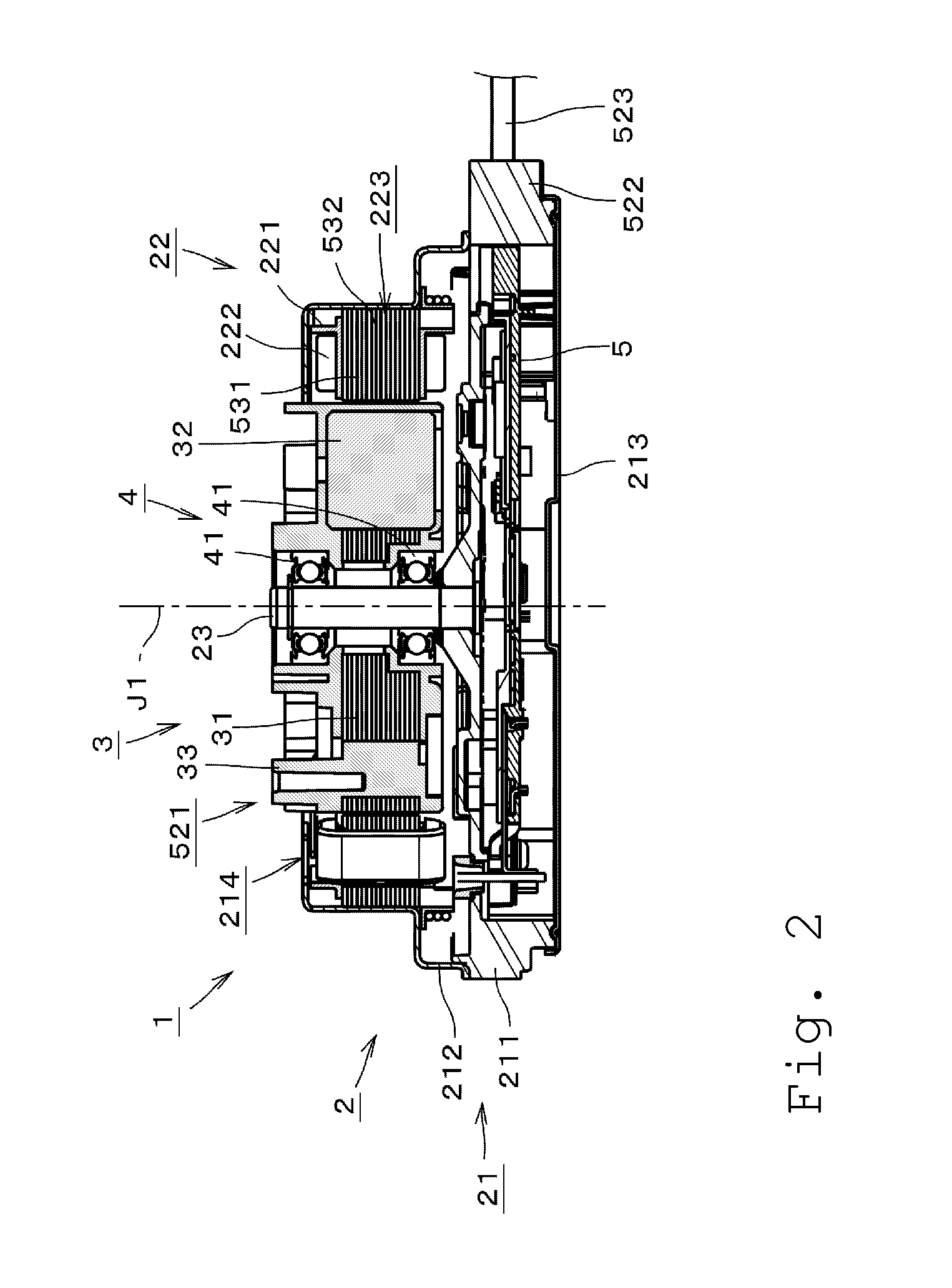
[0027]Herein, in the direction of the center axis J1 of the motor 1, the upper side shown in FIG. 2 is simply referred to as “upper side,” and the lower side thereof is simply referred to as “lower side.” Also, the upper and lower directions do not necessarily refer to the positional relations or directions when the motor is actually assembled and installed to any equipment. Further, a direction parallel to the center axis J1 is simply referred to as “axial direction,” the radial direction having its center on the center axis J1 is simply referred to as “radial direction,” and the circumferential direction having its center on the center axis J1 is simply referred to as “circumferential direction.”

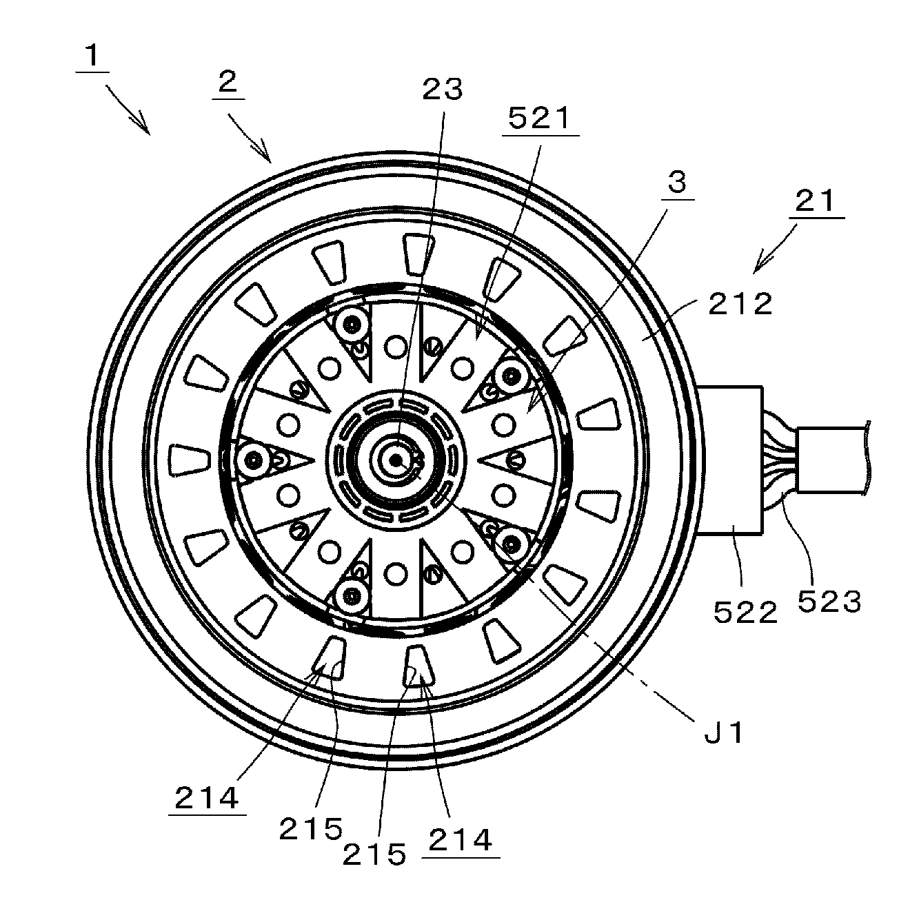
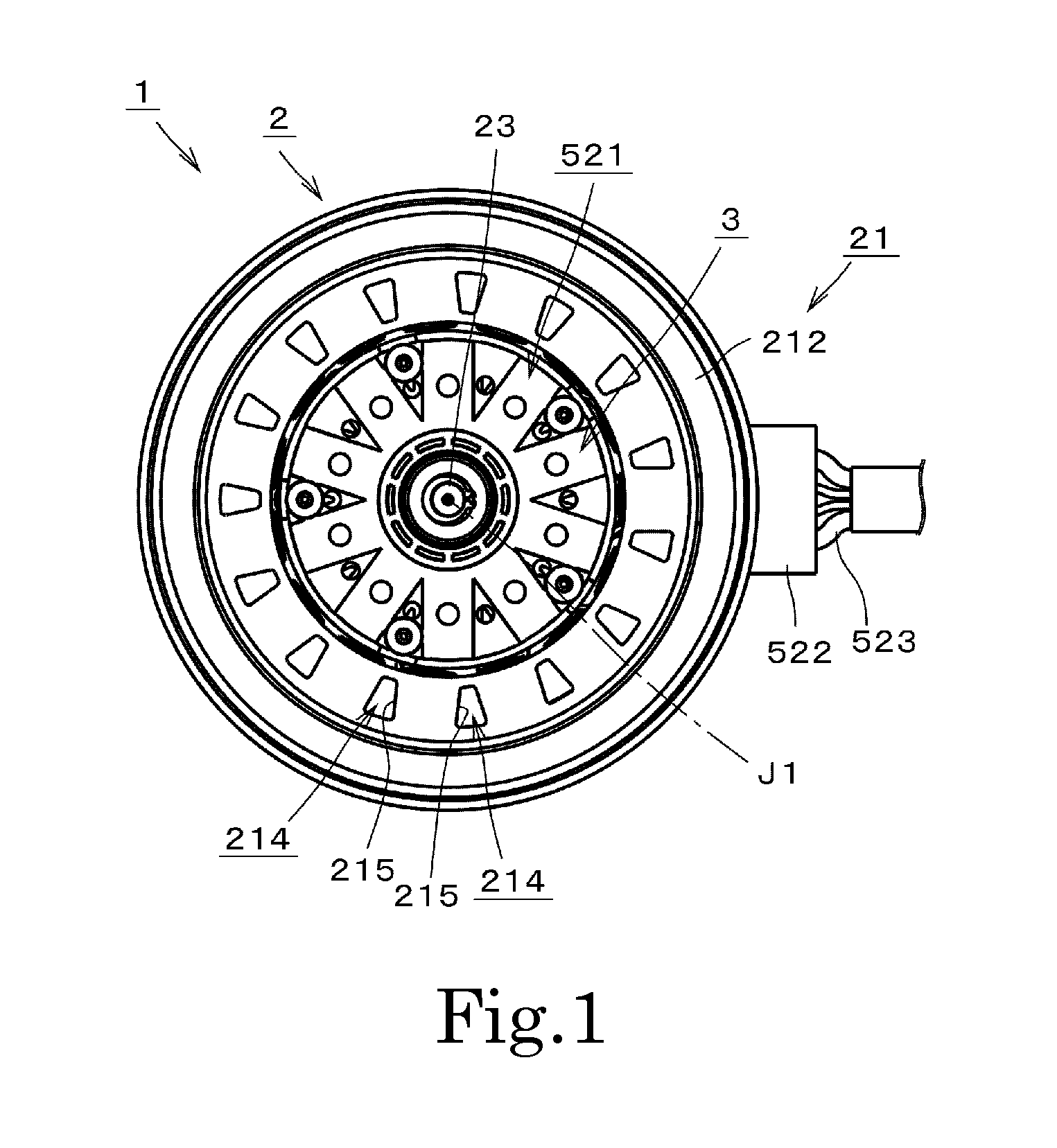
[0028]FIG. 1 is a top view which illustrates a motor 1 according to an exemplary first preferred embodiment of the present disclosure. FIG. 2 is a vertical sectional view of the motor 1. A parallel diagonal line is omitted from the section details. Motor 1 is an inner rotor type brushless ...


PUM


Abstract

The motor according to the present disclosure comprises a rotary unit, a stationary unit disposed around the rotary unit, and a bearing mechanism which rotatably supports the rotary unit relative to the stationary unit. The rotary unit comprises a plurality of magnets. The stationary unit comprises a stator disposed around the rotary unit, and a cover which is electrically conductive and covers a top surface of the stator, and the stator comprises a stator core which includes a plurality of teeth and a core back, and a coil which is wound around the stator core via an insulator. The cover has openings on at least one area of a circumferential interval between neighboring teeth when seen in a top view, and the cover is connected to a ground potential.

Description

BACKGROUND OF THE INVENTION[0001]1. Field of the Invention[0002]The present disclosure relates to an electric motor.[0003]2. Description of the Related Art[0004]From the past, such a type of a motor has been known, in which a structure is provided for releasing heat from the inside of the motor, especially from a stator or a circuit board, by providing an air inlet hole and an air outlet hole to a motor housing, and creating cooling air flow by an air pressure difference formed between around the air inlet hole and around the air outlet hole.[0005]For example, in the motor disclosed in U.S. Pat. No. 7,977,831, a motor housing has air holes. Further, due to air pressure differences between the air inlet holes provided at the bottom of the motor and openings in an air gap, air flows in the motor and releases the heat inside the motor through the air gap.SUMMARY OF THE INVENTION[0006]Presently, numerous electronic components are mounted on a vehicle due to the electrification of automo...

Claims


Application Information

Patent Timeline
Patent Type & Authority Applications(United States)
IPC IPC(8): H02K11/02H02K1/27H02K11/40H02K5/02H02K9/02H02K5/20H02K5/22
CPCH02K11/02H02K5/20H02K1/27H02K11/40H02K5/02H02K9/02H02K5/225H02K11/022H02K7/083H02K5/207H02K1/276H02K11/0141
Inventor FURUTACHI, EIJIFUJIWARA, HIROKI
Owner NIPPON DENSAN CORP
Why Eureka
Try Eureka