
Fixing mechanism and electronic device with heat dissipating function

a technology of electronic devices and fixing mechanisms, which is applied in the direction of machines/engines, machine supports, liquid fuel engines, etc., can solve the problems of complicated assembling/disassembly procedures of conventional fixing mechanisms, deceleration of operation processing speed of electronic devices, and inconvenient assembly/disassembly procedures, etc., to achieve the effect of avoiding heat dissipation efficiency, reducing vibration of fan units, and increasing airflow guiding

Active Publication Date: 2016-08-11
WISTRON CORP
View PDF5 Cites 8 Cited by
  • Summary
  • Abstract
  • Description
  • Claims
  • Application Information

AI Technical Summary

Benefits of technology

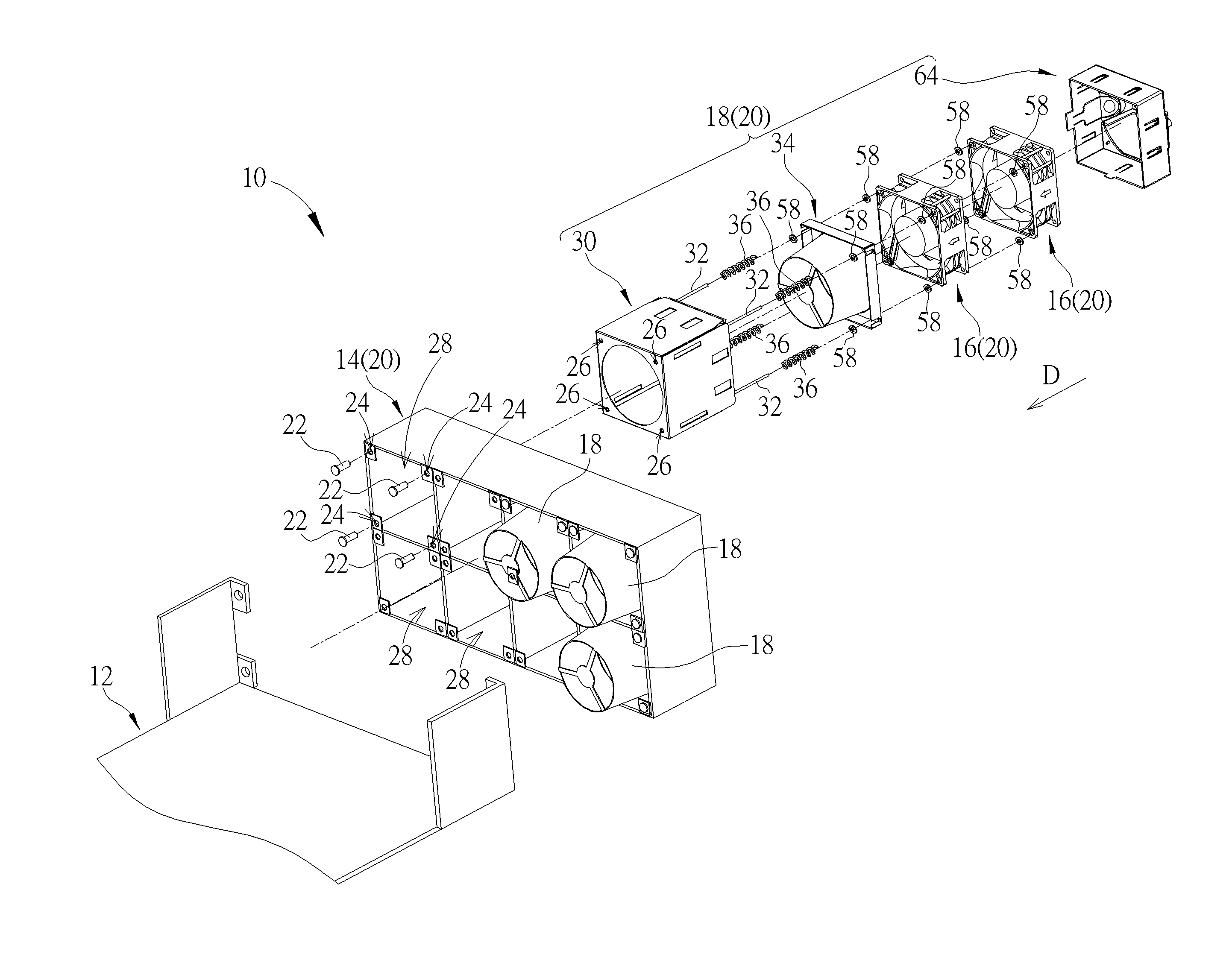
The present invention provides a fixing mechanism for quickly and easily assembling / disassembling fan units with an electronic device. The fixing mechanism combines multiple fan units in series or parallel connection to increase airflow guiding ability. The mechanism has a guiding portion that aligns with the fan unit outlet, regardless of the number of fan units inside the casing. The mechanism includes a resilient component that pushes the fan units tightly against the casing, reducing vibration. The mechanism allows for easy assembly and disassembly without tools and can adjust the number of fan units based on need.

Problems solved by technology

With the advanced technology, the electronic device generates heat due to the progressive operational processing function, and operational processing speed of the electronic device may be decelerated since the heat cannot be dissipated effectively.
The conventional fixing mechanism utilizes the bolts, the screws and / or the rivets to lock the fan unit on the supporter, assembling / disassembling procedures of the conventional fixing mechanism is complicated and inconvenient, and does not conform to actual demand nowadays.

Method used


Image

  • Fixing mechanism and electronic device with heat dissipating function
  • Fixing mechanism and electronic device with heat dissipating function
  • Fixing mechanism and electronic device with heat dissipating function

Examples


Embodiment Construction

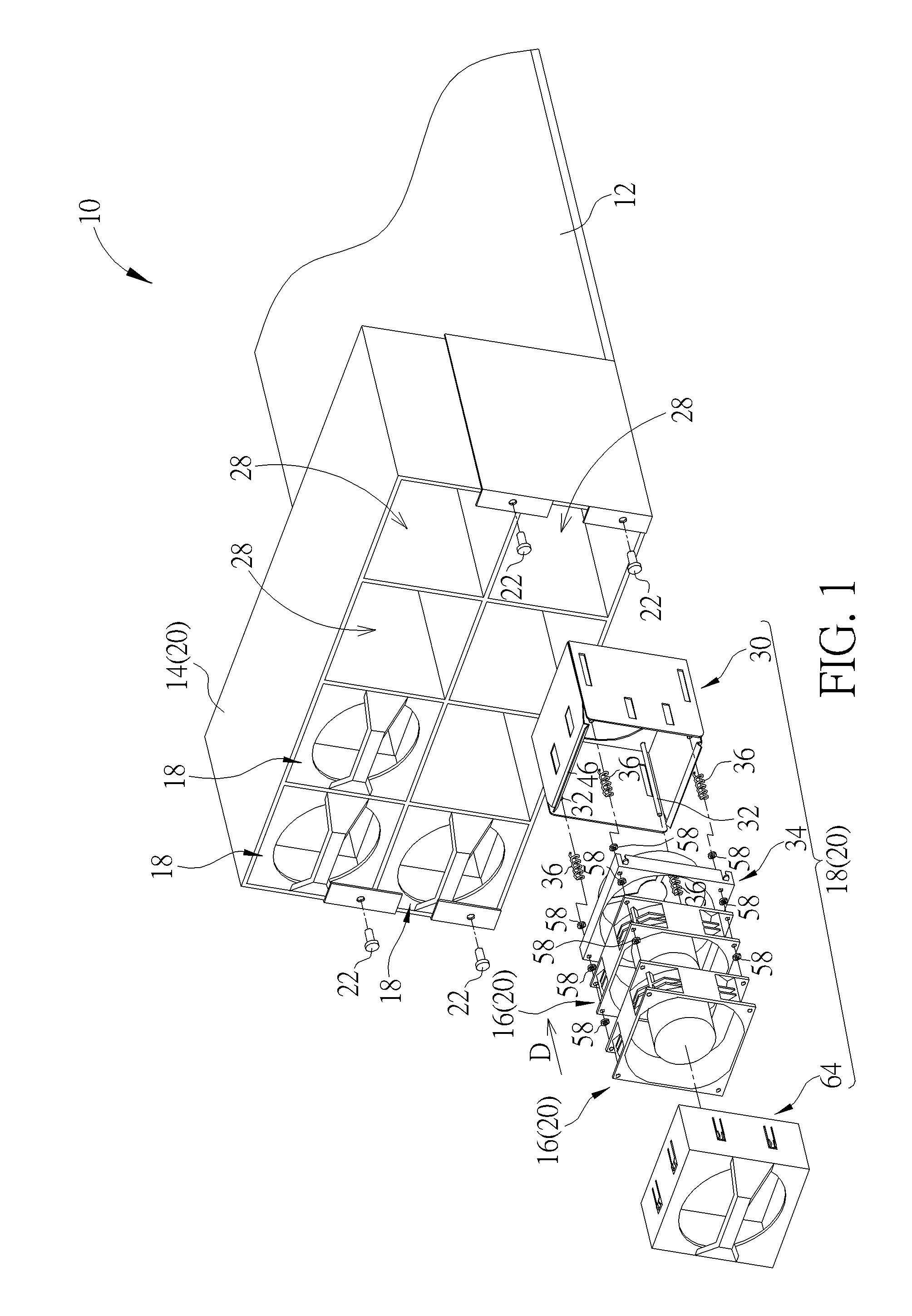
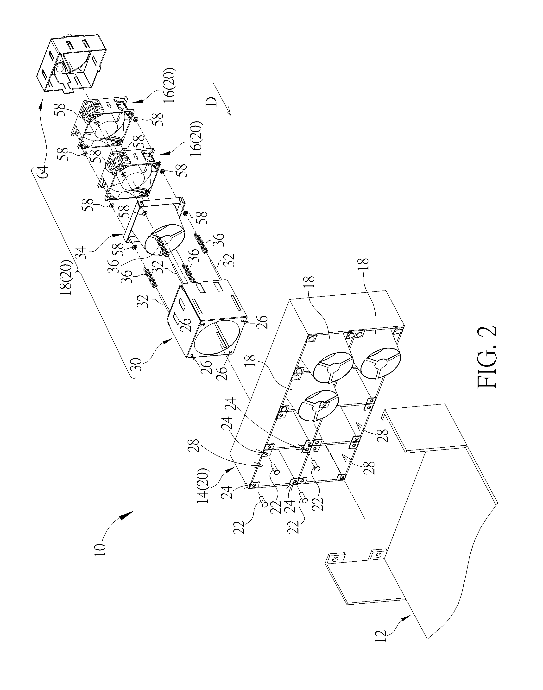
[0028]Please refer to FIG. 1, FIG. 2 and FIG. 9. FIG. 1 and FIG. 2 respectively are diagrams of an electronic device 10 in different views according to an embodiment of the present disclosure. FIG. 9 is a diagram of an electronic device 10′ according to another embodiment of the present disclosure. The electronic device 10 includes a base 12, a supporter 14, a plurality of fan units 16 and a plurality of fixing mechanisms 18. The electronic device 10 can be a server apparatus. The base 12 is utilized to hold several heat-generating components, such as the circuit board, the hard disk and the processor, of the server apparatus. One or more fan units 16 can be installed inside each fixing mechanism 18 according to design demand. The plurality of fixing mechanisms 18 can be detachably disposed on the supporter 14 to form a fan module 20. The fan module 20 is an independent structure with portable convenience. The fan module 20 is disposed on the base 12, and a locking component 22 pass...


PUM


Abstract

An electronic device with heat dissipating function has a fixing mechanism, and the fixing mechanism includes a casing, a positioning component, a fixing component and a resilient component. The casing includes a blocking slab, lateral slabs connected with each other, and a constraining portion disposed on the lateral slabs. The positioning component is disposed inside the casing, and a fan unit is slidably disposed on the positioning component. The fixing component includes a contacting portion and a guiding portion. The guiding portion is disposed on the contacting portion, and the contacting portion is slidably disposed on the positioning component. The guiding portion can move in / out of an outlet of the casing. The resilient component is disposed on the positioning component, and pushes the contacting portion to press the fan unit onto the constraining portion.

Description

BACKGROUND OF THE DISCLOSURE[0001]1. Field of the Disclosure[0002]The present disclosure relates to an electronic device with heat dissipating function, and more particularly, to a fixing mechanism capable of assembling / disassembling one or more fan units quickly and conveniently to combine a fan module and an electronic device having the foresaid fixing mechanism for the heat dissipating function.[0003]2. Description of the Prior Art[0004]With the advanced technology, the electronic device generates heat due to the progressive operational processing function, and operational processing speed of the electronic device may be decelerated since the heat cannot be dissipated effectively. The conventional electronic device normally utilizes an air-cooling heat-dissipating module, such as the fan module, to exhaust hot air inside the electronic device. The fan module is combined by a plurality of fan units to increase its heat dissipating efficiency. The fan module includes a plurality of...

Claims


Application Information

Patent Timeline
IPC IPC(8): H05K7/20F16M13/02
CPCF16M13/02H05K7/20172F04D29/646
Inventor LI, CHEN-YU
Owner WISTRON CORP
Learn More