Semiconductor high-power light-emitting module with heat isolation

a high-power, light-emitting module technology, applied in semiconductor devices, semiconductor/solid-state device details, lighting and heating apparatus, etc., can solve the problems of halogen lamps, how to solve heat dissipation problems, and heat generated by high-power light-emitting diodes, so as to prevent the efficiency of heat dissipation members, enhance heat dissipation efficiency, and reduce the influence of hea

Active Publication Date: 2012-06-05
ENRAYTEK OPTOELECTRONICS
View PDF21 Cites 2 Cited by
  • Summary
  • Abstract
  • Description
  • Claims
  • Application Information

AI Technical Summary

Benefits of technology

[0010]According to the preferred embodiment, the semiconductor light-emitting module of the invention can be applied to a headlight of an automobile. The heat-dissipating member can be engaged on the body (e.g. the frame behind the bumper or the shell) of the automobile. Further, the position of the headlight is much closer to those of the apparatuses (e.g. an engine) with high temperature, so the semiconductor light-emitting module includes the isolator member for preventing the efficiency of the heat-dissipating member from the influence of the environment temperature produced by the above-mentioned apparatuses. Moreover, an isolator sleeve is used to cover the heat-conducting device between the diode light-emitting device and the contact portion to further reduce the influence of the heat generated by the above-mentioned apparatuses toward the environment temperature at the heat-dissipating member. In order to enhance heat dissipation efficiency, a plurality of fins are formed on the second side of the heat-dissipating member. Besides, the semiconductor light-emitting module further includes a control circuit which is electrically connected to the diode light-emitting device for controlling the diode light-emitting device to emit the light.
[0011]Accordingly, the semiconductor light-emitting module of the invention utilizes an isolator member to prevent the heat dissipation efficiency of the heat-dissipating member of the semiconductor light-emitting module from the influence of the environment with high temperature, so that the heat-dissipating member is capable of dissipating heat effectively in an environment with low temperature. If applied in the headlight of the automobile, the heat-dissipating member of the semiconductor light-emitting module of the invention can be integrally designed with the shell, which is not only aesthetic but also functional. Furthermore, by dissipating the heat generated during the operation of the diode light-emitting device out of the body of the automobile to the environment with lower temperature by means of the heat-dissipating member, it is able to dispose the high-power semiconductor light-emitting module in the headlight of the automobile.

Problems solved by technology

However, the heat which is generated by a high-power light-emitting diode also generates a lot of heat, so how to solve the problem of heat dissipation becomes a main issue in the field.
For example, halogen lamps are the mainstream in the traditional automobile headlight market, but the halogen lamps have disadvantages such as insufficient illumination and short service life.
It will cause the light-emitting diode to bear the heat generated by apparatuses such as the engine and thus become difficult to dissipate heat.

Method used


Image

  • Semiconductor high-power light-emitting module with heat isolation
  • Semiconductor high-power light-emitting module with heat isolation
  • Semiconductor high-power light-emitting module with heat isolation

Examples


Embodiment Construction

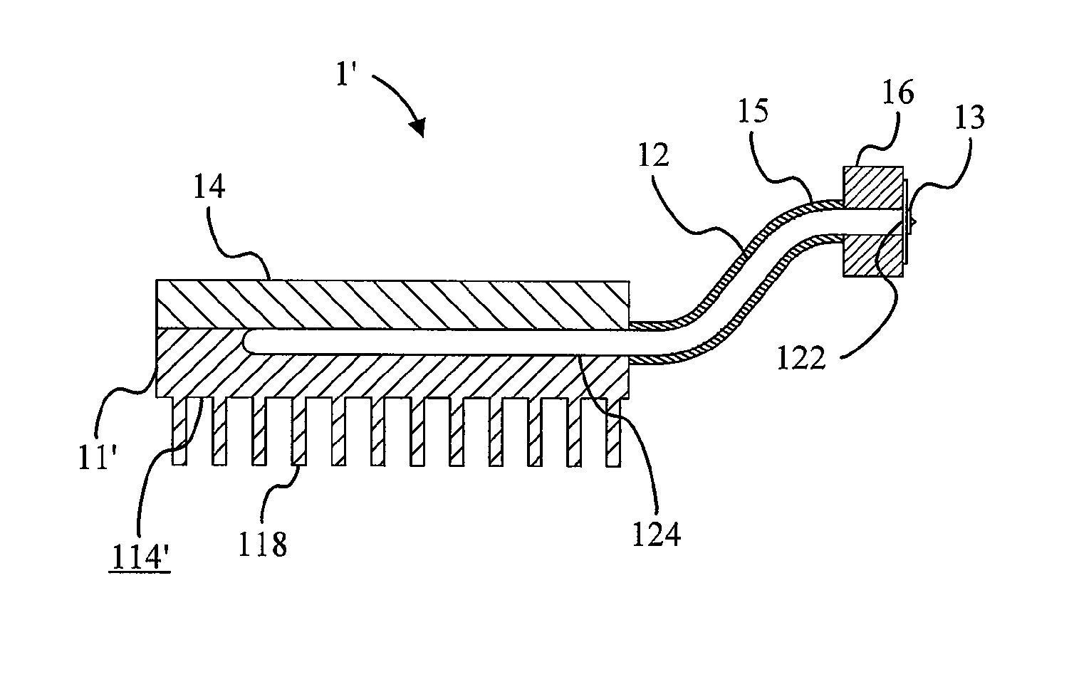
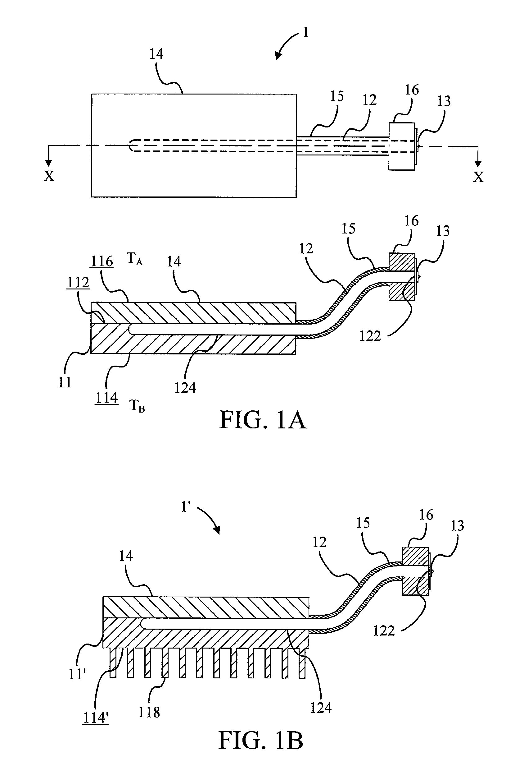
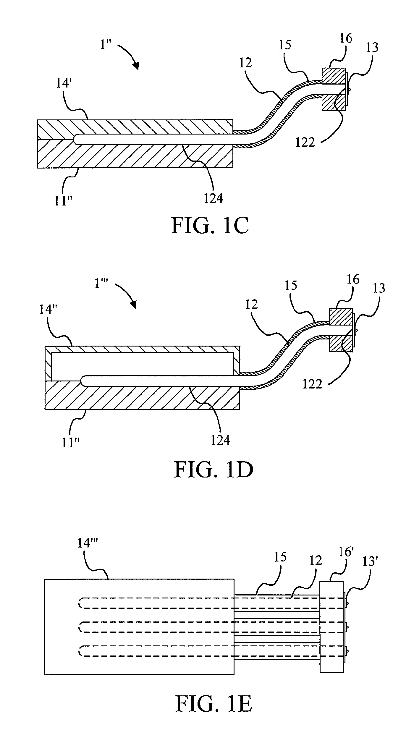
[0026]Please refer to FIG. 1A. FIG. 1A is a schematic diagram illustrating a semiconductor light-emitting module 1 according to a first preferred embodiment of the invention. The lower drawing in FIG. 1A is a cross-sectional view of the upper drawing along line X-X. The semiconductor light-emitting module 1 includes a heat-dissipating member 11, a heat-conducting device 12, a diode light-emitting device 13, an isolator sleeve 15, and a carrier 16. The heat-dissipating member 11 has an isolator member 14 which is coupled to a first side 112 of the heat-dissipating member 11. The heat-dissipating member 11 has a second side 114 opposite to the first side 112. The isolator member 14 has a third side 116 opposite to the first side 112. The environment temperature at the third side 116 is higher than that at the second side 114. The heat-conducting device 12 has a flat end 122 and a contact portion 124. The contact portion 124 is disposed between the heat-dissipating member 11 and the is...


PUM


Abstract

The invention provides a semiconductor high-power light-emitting module including a heat-dissipating member, a heat-conducting device, and a diode light-emitting device. The heat-dissipating member includes an isolator member coupled to a first side of the heat-dissipating member. The heat-dissipating member has a second side opposite to the first side. The isolator member has a third side opposite to the first side. The environment temperature at the third side is higher than that at the second side. The heat-conducting device has a flat end and a contact portion tightly mounted on the heat-dissipating member. The diode light-emitting device is disposed on the flat end of the heat-conducting device. The semiconductor light-emitting module of the invention, applied to a headlamp of an automobile, has properties of saving electricity and long life, and furthermore the capability of integrating the heat-dissipating member into a shell of the automobile is both artistic and practical.

Description

CROSS-REFERENCE TO RELATED APPLICATION[0001]This application claims priority to PCT Application No. PCT / CN06 / 002646, filed Oct. 10, 2006.BACKGROUND OF THE INVENTION[0002]1. Field of the Invention[0003]This invention relates to a semiconductor light-emitting module and, more particularly, to a semiconductor high-power light-emitting module with heat isolation.[0004]2. Description of the Prior Art[0005]Due to the advantages such as power saving, shock-resistance, fast response time, and adaptability for mass production, illumination equipment which applies light-emitting diodes is being researched and developed continuously. However, the heat which is generated by a high-power light-emitting diode also generates a lot of heat, so how to solve the problem of heat dissipation becomes a main issue in the field. Traditionally, a common way to dissipate heat is to put a heat-dissipating member (may includes a plurality of fins) at low temperature environment to dissipate heat. But in many ...

Claims


Application Information

Patent Timeline
Patent Type & Authority Patents(United States)
IPC IPC(8): H01L33/00
CPCF21K9/00F21S48/328F21V29/004F21V29/76F21S48/115F21V29/70F21Y2101/02F21V29/006H01L2224/48091H01L2224/48137H01L2924/00014F21Y2115/10F21S41/143F21S45/47F21V29/51F21S41/153F21K9/20F21S45/48
Inventor CHEN, JEN-SHYAN
Owner ENRAYTEK OPTOELECTRONICS
Why Eureka
Try Eureka