Control apparatus for internal combustion engine

a control apparatus and internal combustion engine technology, applied in the direction of electrical control, ignition automatic control, hybrid vehicles, etc., can solve the problem of response delay in controlling the intake air amount, and achieve the effect of suppressing the response delay in changing over the combustion mode and restraining the thermal efficiency of the internal combustion engin

Active Publication Date: 2017-05-16
TOYOTA JIDOSHA KK
View PDF5 Cites 0 Cited by
  • Summary
  • Abstract
  • Description
  • Claims
  • Application Information

AI Technical Summary

Benefits of technology

[0009]The invention provides a control apparatus for an internal combustion engine that restrains a thermal efficiency of an internal combustion engine from deteriorating as a combustion mode is changed over, and that suppresses a response delay in changing over the combustion mode.
[0011]According to this control apparatus, the combustion mode is changed over in accordance with the first changeover condition that is set based on the predetermined intake air amount at which the thermal efficiency of the internal combustion engine can be maintained before and after changeover of the combustion mode. Therefore, the thermal efficiency of the internal combustion engine can be restrained from deteriorating after the combustion mode is changed over. Besides, in changing over the combustion mode, the air-fuel ratio is changed in a stepped manner through the control of the fuel injection amount. Therefore, the response delay in changing over the combustion mode can be suppressed in comparison with a case where the intake air amount is controlled. Incidentally, maintaining the thermal efficiency means that the thermal efficiency does not deteriorate beyond a permissible range after the combustion mode is changed over. Accordingly, maintaining the thermal efficiency includes a case where the thermal efficiency before changeover of the combustion mode and the thermal efficiency after changeover of the combustion mode are equal to each other, and a case where these thermal efficiencies are confined within the permissible range.
[0012]In the aforementioned aspect of the invention, the torque suppression device may include a motor-generator that transmits a motor torque to the output portion. The ECU may be configured to execute power running control or regenerative control of the motor-generator such that the motor-generator suppresses the fluctuation in the torque of the internal combustion engine. According to this aspect of the invention, when the engine torque has increased as a result of changeover of the combustion mode, the increase in engine torque can be absorbed through regenerative control of the motor-generator. When the engine torque has decreased as a result of changeover of the combustion mode, a deficiency in engine torque can be supplemented through power running control of the motor-generator. Thus, the torque of the output portion of the internal combustion engine can be appropriately maintained during changeover of the combustion mode.
[0014]As described above, with the control apparatus for the internal combustion engine according to the aforementioned aspect of the invention, the combustion mode is changed over in accordance with the first changeover condition that is set based on the predetermined intake air amount at which the thermal efficiency of the internal combustion engine can be maintained before and after changeover of the combustion mode. Therefore, the thermal efficiency of the internal combustion engine can be restrained from deteriorating after changeover of the combustion mode. Besides, in changing over the combustion mode, the air-fuel ratio is changed in a stepped manner by changing the fuel injection amount. Therefore, the response delay in changing over the combustion mode can be suppressed in comparison with a case where the intake air amount is controlled.

Problems solved by technology

Besides, there is a response delay in controlling the intake air amount.

Method used


Image

  • Control apparatus for internal combustion engine
  • Control apparatus for internal combustion engine
  • Control apparatus for internal combustion engine

Examples


Embodiment Construction

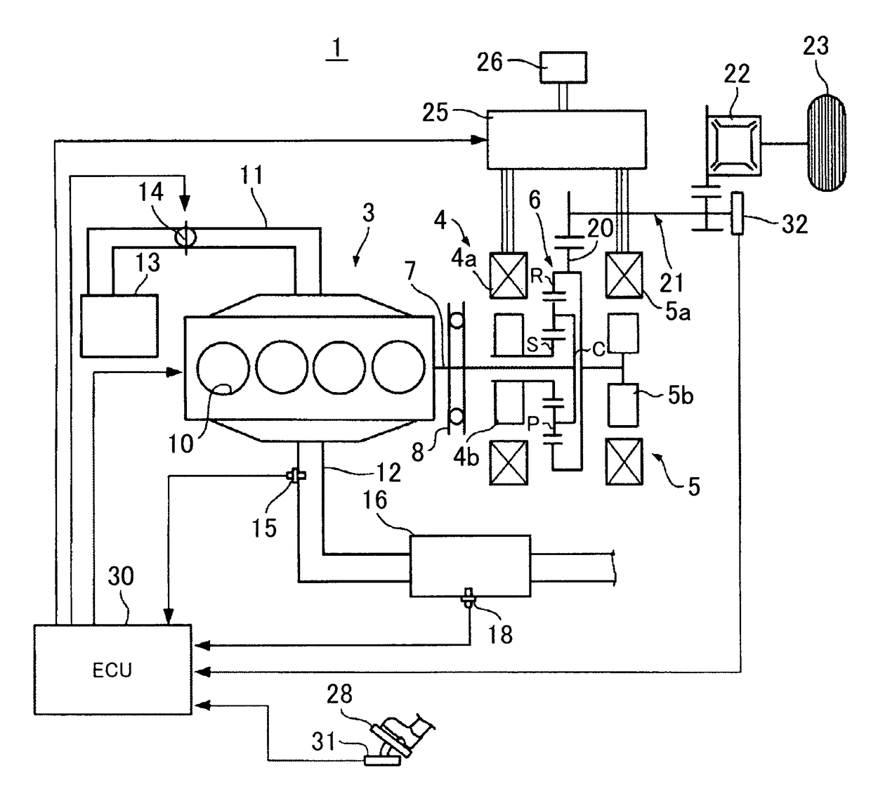
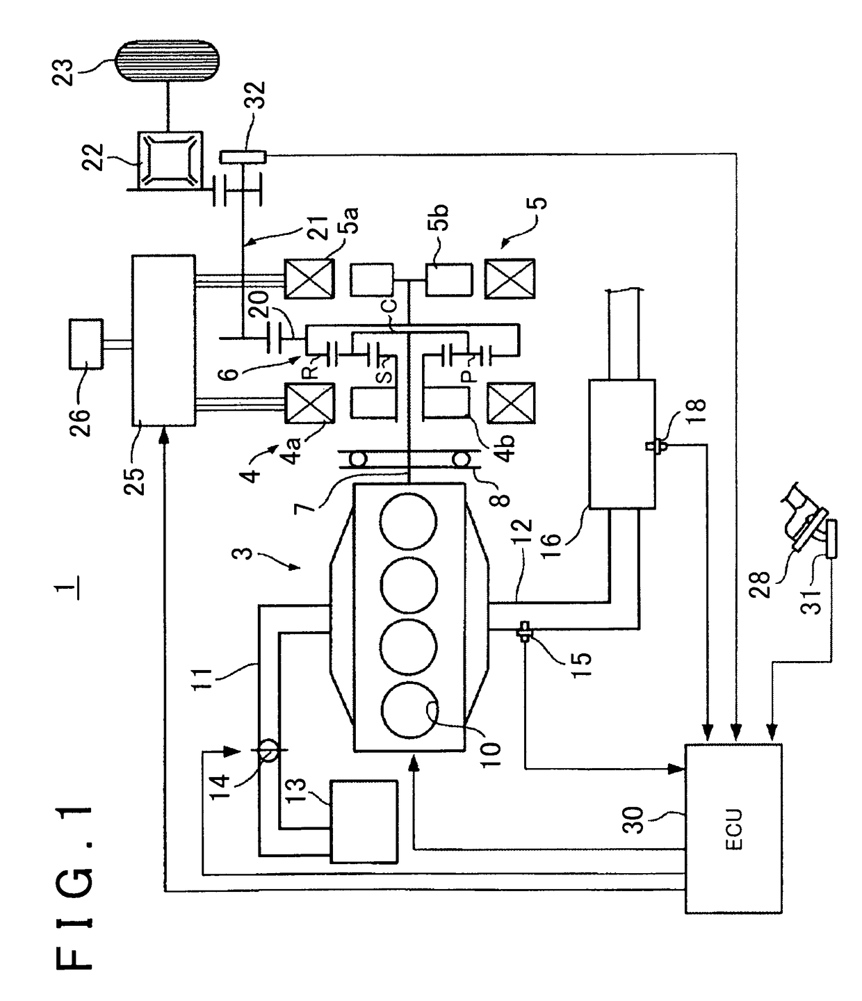
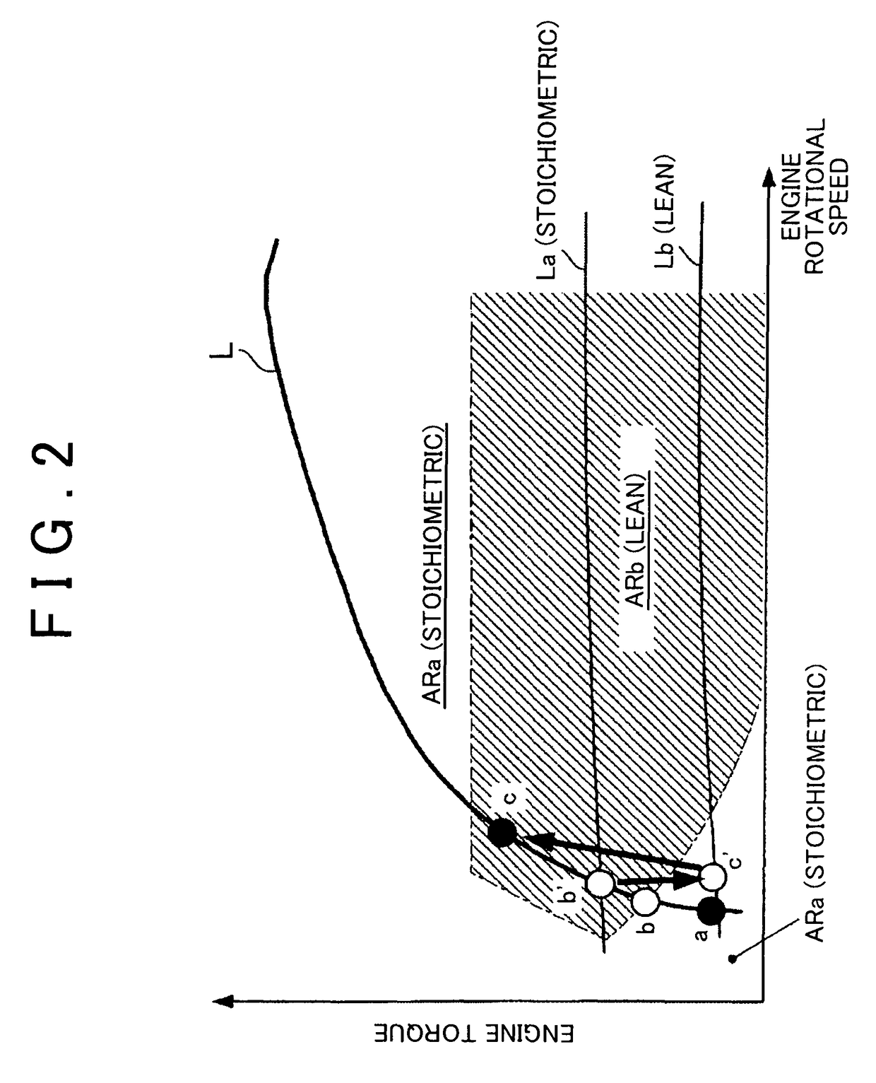
[0024]As shown in FIG. 1, a vehicle 1 is configured as a hybrid vehicle having a combination of a plurality of power sources. The vehicle 1 is equipped with an internal combustion engine 3 and two motor-generators 4 and 5 as power sources for running. The internal combustion engine 3 is an in-line four-cylinder spark ignition internal combustion engine that is equipped with four cylinders 10. The internal combustion engine 3 is configured as a so-called lean burn engine, and can change over the combustion mode between lean combustion and stoichiometric combustion. Lean combustion is a combustion mode in which an air-fuel ratio that is set on a leaner side than a theoretical air-fuel ratio is regarded as a target. Stoichiometric combustion is a combustion mode in which the theoretical air-fuel ratio, which is on a richer side than the air-fuel ratio of lean combustion, or an air-fuel ratio in the vicinity thereof is regarded as a target.

[0025]An intake passage 11 and an exhaust passa...


PUM


Abstract

A control apparatus for an internal combustion engine is provided. The control apparatus includes an ECU. The ECU is configured to change, in a stepped manner, an air-fuel ratio of the internal combustion engine so as to change over a combustion mode of the internal combustion engine between lean combustion and stoichiometric combustion, when an operating point of the internal combustion engine satisfies a first changeover condition that is defined by a rotational speed and a torque of the internal combustion engine. The first changeover condition is defined by the rotational speed and the torque that correspond to a predetermined intake air amount at which a thermal efficiency of the internal combustion engine is maintained before and after changeover of the combustion mode.

Description

INCORPORATION BY REFERENCE[0001]The disclosure of Japanese Patent Application No. 2014-133851 filed on Jun. 30, 2014 including the specification, drawings and abstract is incorporated herein by reference in its entirety.BACKGROUND OF THE INVENTION[0002]1. Field of the Invention[0003]The invention relates to a control apparatus for an internal combustion engine that is applied to an internal combustion engine that can change over a combustion mode between lean combustion and stoichiometric combustion.[0004]2. Description of Related Art[0005]There is known a lean burn engine in which lean combustion can be carried out with a target air-fuel ratio set on a leaner side than a theoretical air-fuel ratio. In the lean burn engine, stoichiometric combustion is carried out at the time of acceleration, at the time of low rotation and low load, etc. With stoichiometric combustion, the internal combustion engine carries out combustion at the theoretical air-fuel ratio, which is on a richer side...

Claims


Application Information

Patent Timeline
Patent Type & Authority Patents(United States)
IPC IPC(8): F02D41/14F02P5/04F02D29/02F02D41/10F02P5/15F02D37/02H02P9/02F02D41/00F02D41/30F02D41/04
CPCH02P9/02F02D29/02F02D37/02F02D41/0002F02D41/107F02D41/307F02P5/045F02P5/1504F02D41/045F02D2200/101F02D2200/501F02D2250/21F02D2250/24Y02T10/42Y02T10/46B60K6/445B60W10/06B60W10/08B60W20/00B60W30/20B60W2030/206B60W2710/0622B60W2710/083B60W20/11Y02T10/40Y02T10/62
Inventor KANNO, YOSHIHITO
Owner TOYOTA JIDOSHA KK
Why Eureka
Try Eureka