
Automatic bifurcation latch systems for a thrust reverser

a technology of automatic bifurcation latch and thrust reverser, which is applied in the direction of machines/engines, aircraft power plant components, aircraft power plants, etc., can solve the problems of large, unacceptable deflection, and sealing between the if and the engine to be broken, and achieves major damage and safety concerns

Active Publication Date: 2016-08-25
ROHR INC
View PDF12 Cites 3 Cited by
  • Summary
  • Abstract
  • Description
  • Claims
  • Application Information

AI Technical Summary

Benefits of technology

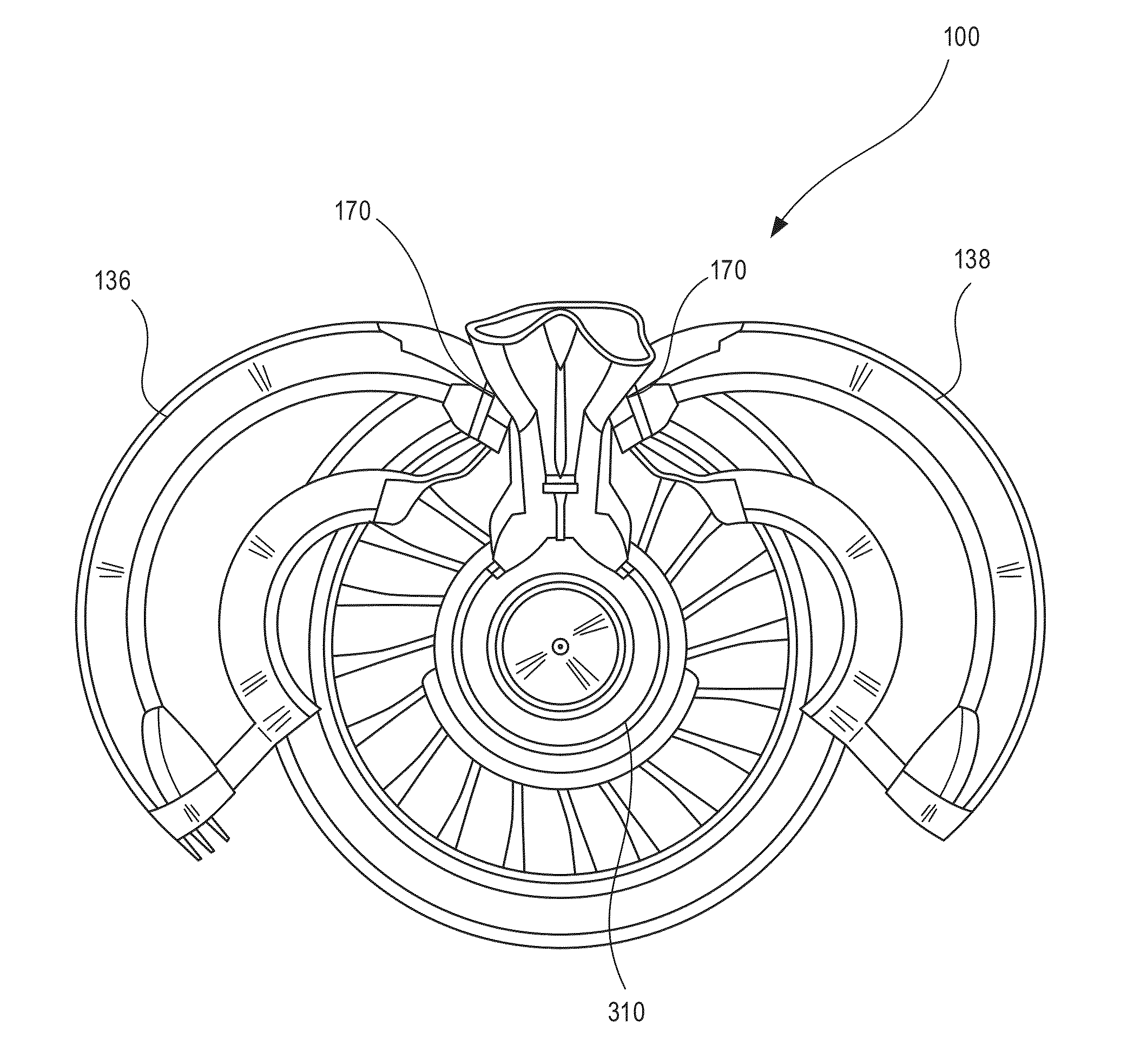
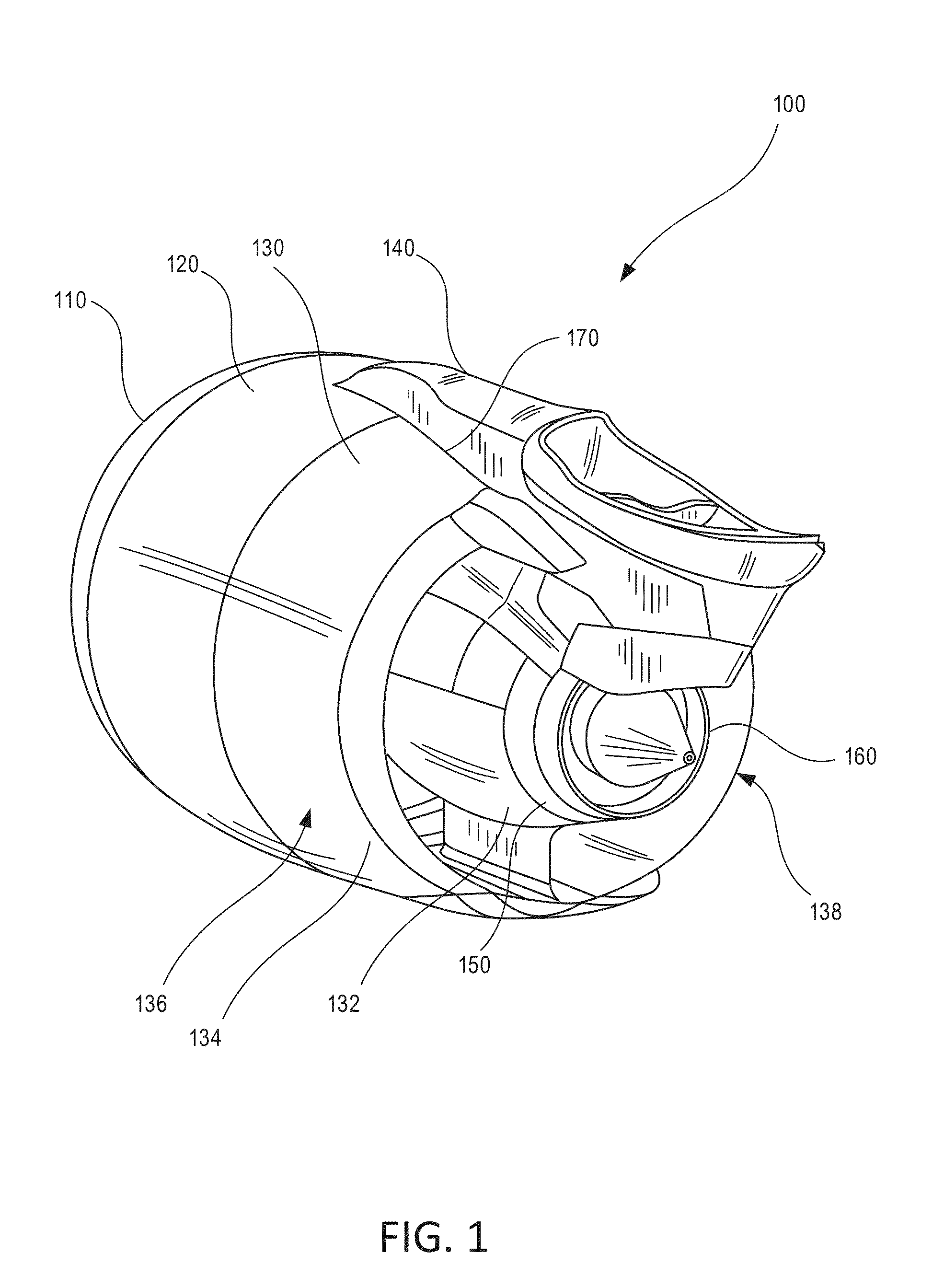
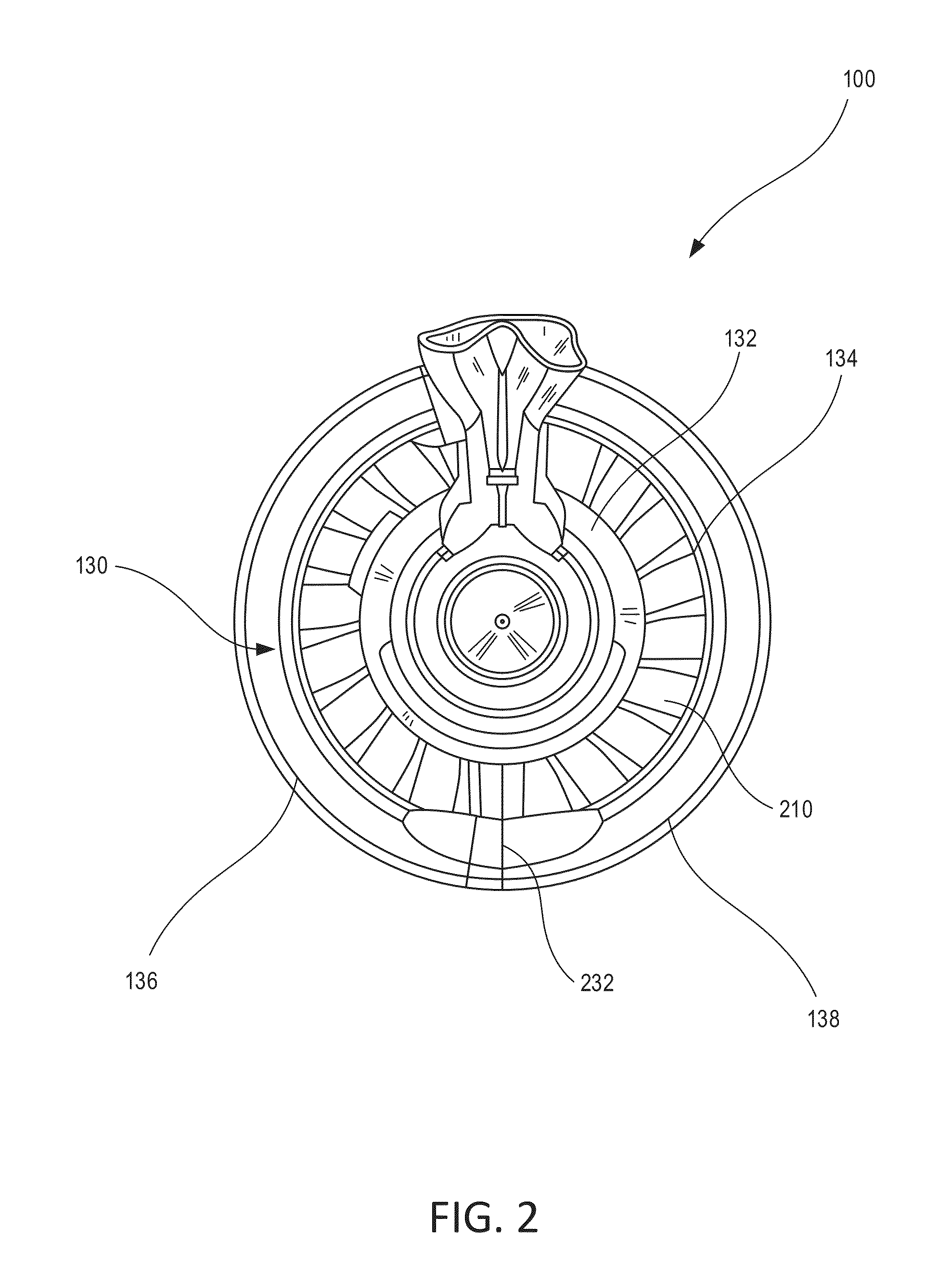
The patent describes an aircraft nacelle with a thrust reverser system. The nacelle includes a locking mechanism that maintains a seal in the event of a burst duct. The locking mechanism is designed to automatically engage when the thrust reverser half is opened and disengage when the half is closed. This mechanism helps to prevent damage to the nacelle in the event of a burst duct. The locking mechanism includes a rack and pinion system and a latch that is coupled to the pylon and movable between a locked and unlocked position. The latch automatically unlocks when the thrust reverser half is opened, allowing for relative movement between the two parts. The aircraft nacelle also includes a bumper that contacts the latch in response to an increase in pressure in the core compartment.

Problems solved by technology

In these conditions, the radially outward net positive pressure on the IFS may lead to large, unacceptable deflections.
These deflections may cause the sealing between the IFS and the engine to be broken.
This condition could lead to air scooping the structure leading to major damage and safety concerns.
Latches have been proposed and used to reinforce the IFS by either latching the IFS to the pylon or engine, or latching the IFS halves to each other, but these existing latches suffer from various disadvantages or insufficiencies.
For example, the latches may require remote engagement because there is no way to physically access the latch to manipulate it between its open and closed positions.
Remote engagement presents many challenges, because the remote engagement mechanism or system can be complex, cumbersome to integrate into the structure, and can be unreliable.

Method used


Image

  • Automatic bifurcation latch systems for a thrust reverser
  • Automatic bifurcation latch systems for a thrust reverser
  • Automatic bifurcation latch systems for a thrust reverser

Examples


Embodiment Construction

[0017]The detailed description of various embodiments herein makes reference to the accompanying drawings, which show various embodiments by way of illustration. While these various embodiments are described in sufficient detail to enable those skilled in the art to practice the inventions, it should be understood that other embodiments may be realized and that logical, chemical and mechanical changes may be made without departing from the spirit and scope of the inventions. Thus, the detailed description herein is presented for purposes of illustration only and not of limitation. For example, the steps recited in any of the method or process descriptions may be executed in any order and are not necessarily limited to the order presented. Furthermore, any reference to singular includes plural embodiments, and any reference to more than one component or step may include a singular embodiment or step. Also, any reference to attached, fixed, connected or the like may include permanent,...


PUM


Abstract

A nacelle may include a pylon and a thrust reverser having an inner fixed structure. A locking mechanism may automatically engage and prevent relative movement between a thrust reverser half and the pylon. A bumper may be coupled to the inner fixed structure. The locking mechanism may limit deflections between the thrust reverser and the pylon in response to a burst duct. The locking mechanism may allow the thrust reverser halves to be opened for access to the engine.

Description

FIELD[0001]The disclosure generally relates to turbofan propulsion systems for aircraft. More particularly, the disclosure relates to deflection limiting systems for a thrust reverser in a nacelle for a turbofan propulsion system.BACKGROUND[0002]Modern aircraft may utilize one or more turbofan propulsion systems powered by a gas turbine engine. The propulsion system may include a nacelle, which is a system of components that house the engine and its ancillary systems, and help form aerodynamic surfaces for flight, including a fan bypass air duct. Often, the nacelle includes a thrust reverser. The thrust reverser includes an inner fixed structure (“IFS”) surrounding the engine which forms part of the interior surface of the bypass air duct through the thrust reverser. The IFS defines a core compartment that surrounds the engine. The engine may comprise various high pressure ducts, such as a compressor bleed duct and an anti-ice air duct. The ducts may hold high pressure, high tempera...

Claims


Application Information

Patent Timeline
Patent Type & Authority Applications(United States)
IPC IPC(8): F02K1/54B64D33/04
CPCB64D33/04F02K1/54B64D29/06
Inventor BROWN, KEITH T.
Owner ROHR INC
Learn More