System and method for heating a pipeline using heated lines

Inactive Publication Date: 2016-08-25
THERMA STOR LLC
View PDF7 Cites 3 Cited by
  • Summary
  • Abstract
  • Description
  • Claims
  • Application Information

AI Technical Summary

Benefits of technology

[0003]According to embodiments of the present disclosure, disadvantages and problems ass

Problems solved by technology

Often pipelines are heated by makeshift solutions that are cumbersome, dif

Method used


Image

  • System and method for heating a pipeline using heated lines
  • System and method for heating a pipeline using heated lines
  • System and method for heating a pipeline using heated lines

Examples


Example

DETAILED DESCRIPTION OF THE DRAWINGS

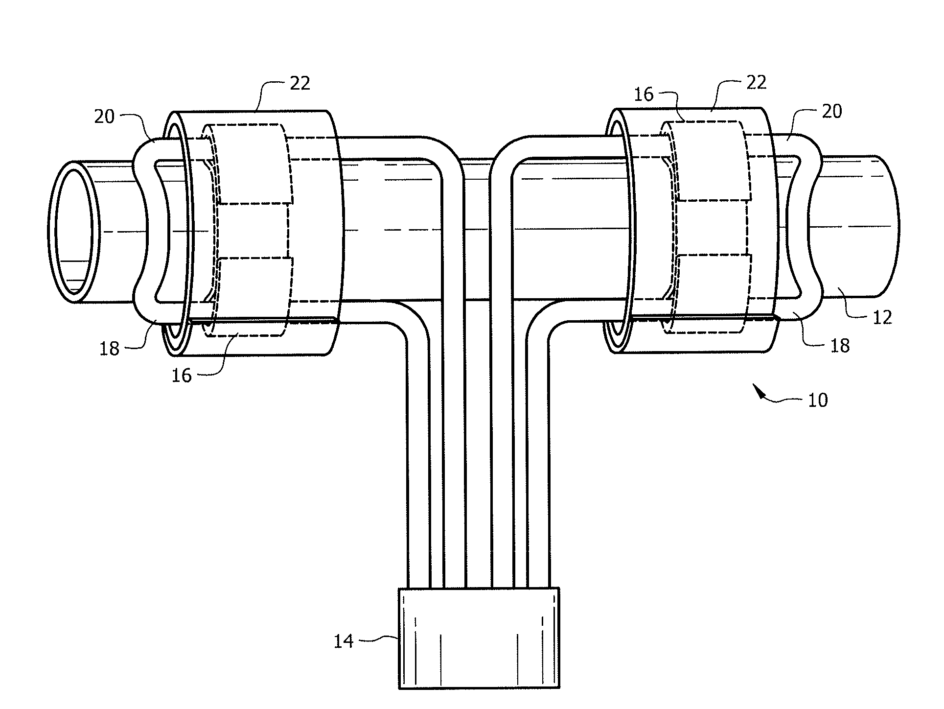
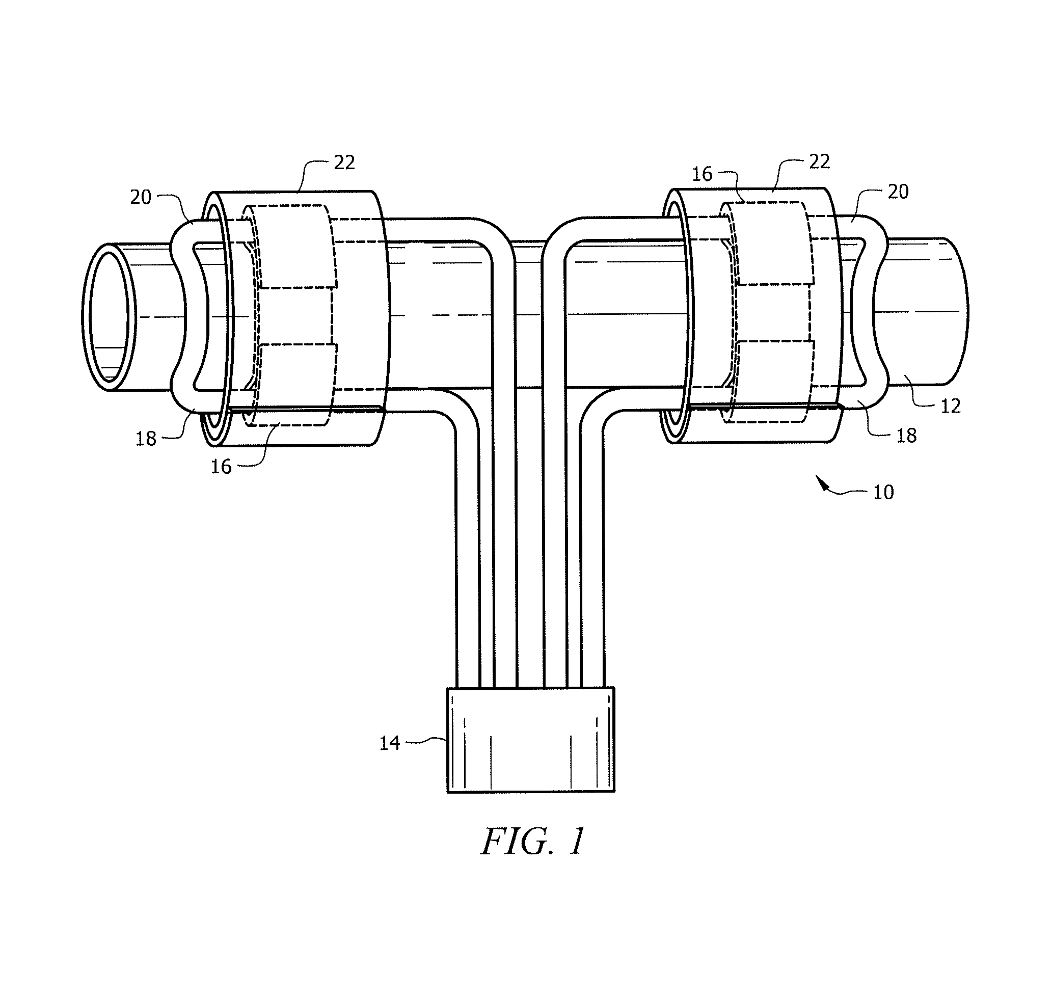
[0017]FIG. 1 illustrates a top-down view of one embodiment of system 10 for heating a pipeline 12 using a heater 14. System 10 includes straps 16, a supply line 18, a return line 20, and insulated blankets 22. Pipeline 12 may transport any fluids such as water, oil, liquefied natural gas, sewage, slurry, biofuels, etc. In order to prevent the fluids inside pipeline 12 from freezing, system 10 uses heated fluid flowing through supply line 18 and return line 20 to keep the pipeline warm. In system 10, heater 14 heats the fluid which flows through supply line 18. Supply line 18 runs alongside pipeline 12 and is positioned in thermal contact with pipeline 12 using straps 16. In one embodiment, supply line 18 eventually loops over pipeline 12 and is coupled to return line 20. Return line 20 carries the heated fluid back to heater 14. Return line 20 runs alongside pipeline 12 and is positioned in thermal contact with pipeline 12 using straps 16. One of ...


PUM


Abstract

A system for heating a pipeline comprises a heater operable to heat a fluid, a supply line and a return line. A first strap is positioned at a first portion of a pipeline. A first pocket of the first strap holds the supply line in thermal contact with the first portion of the pipeline. A second pocket of the first strap holds the return line in thermal contact with the first portion of the pipeline. A second strap is positioned at a second portion of the pipeline. A third pocket of the first strap holds the supply line in thermal contact with the second portion of the pipeline. A fourth pocket holds the return line in thermal contact with the second portion of the pipeline.

Description

TECHNICAL FIELD[0001]This invention relates generally to a heating system and specifically to a system and method for heating a pipeline using heated lines.BACKGROUND OF THE INVENTION[0002]Pipelines are used in various industries to transport fluids. These pipelines are sometimes located in areas with very low temperatures. It is often necessary to keep pipelines warm to prevent the fluids inside the pipeline from freezing. Often pipelines are heated by makeshift solutions that are cumbersome, difficult to install and deploy, and usually result in substantial heat loss.SUMMARY OF THE INVENTION[0003]According to embodiments of the present disclosure, disadvantages and problems associated with previous pipeline heating systems and methods may be reduced or eliminated.[0004]In one embodiment, a system for heating a pipeline comprises a heater operable to heat a fluid, a supply line and a return line. A first strap is positioned at a first portion of a pipeline. A first pocket of the fi...

Claims


Application Information

Patent Timeline
IPC IPC(8): F24H1/14H05B3/00H05B3/06H05B3/58
CPCF24H1/142H05B3/06H05B3/0014H05B3/58F16L53/32
Inventor MYERHOLTZ, JR., ROBERT M.DANCEY, LARRY L.
Owner THERMA STOR LLC
Why Eureka
Try Eureka