Geothermal power plant

a geothermal power plant and power generation technology, applied in geothermal energy generation, directional drilling, lighting and heating apparatus, etc., can solve the problems of difficult control of fracturing process, difficult control of water flow in heat exchanger, difficult control of water flow, etc., to reduce drilling cost and risk, cost reduction, and optimize energy output

Active Publication Date: 2016-08-25
GEOVARME AS
View PDF1 Cites 9 Cited by
  • Summary
  • Abstract
  • Description
  • Claims
  • Application Information

AI Technical Summary

Benefits of technology

The present invention provides a design for a geothermal energy plant that combines supply and return holes, reducing drilling costs and risk. The design optimizes drilling patterns to maximize energy output while minimizing drilling costs. The design can be adapted for different temperature gradients and can be established based on the actual operating conditions of the plant. The invention also includes a method for designing the geothermal energy plant.

Problems solved by technology

The technical problem addressed in this patent text is how to efficiently extract heat from hot dry rock (HDR) formations without the need for a large number of drilling wells, which can be costly and difficult to control. The challenge is to design a system that can maximize heat transfer from the rock while minimizing drilling costs.

Method used


Image

  • Geothermal power plant
  • Geothermal power plant
  • Geothermal power plant

Examples


Embodiment Construction

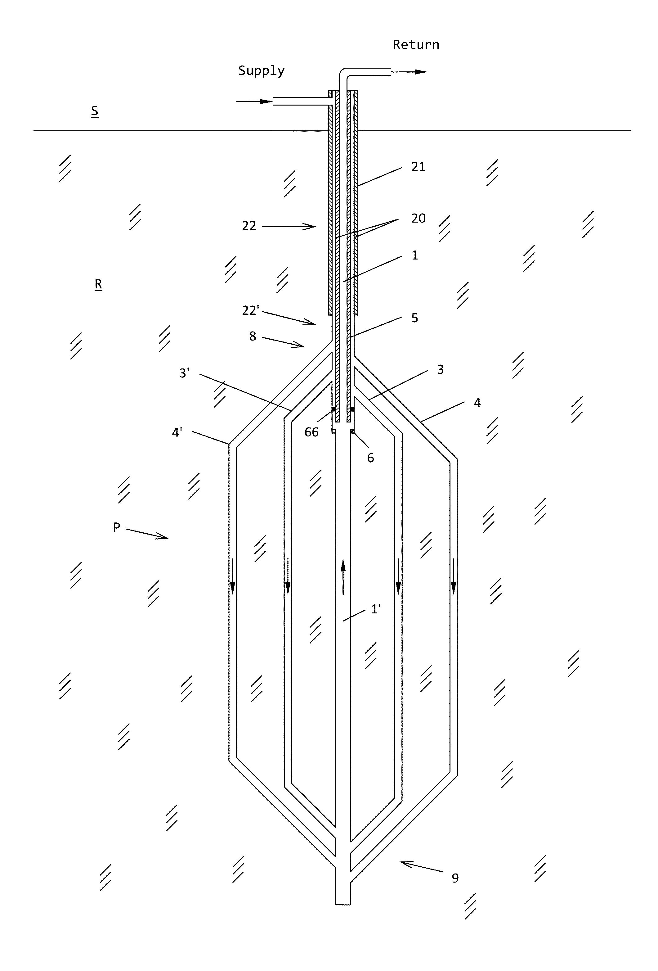
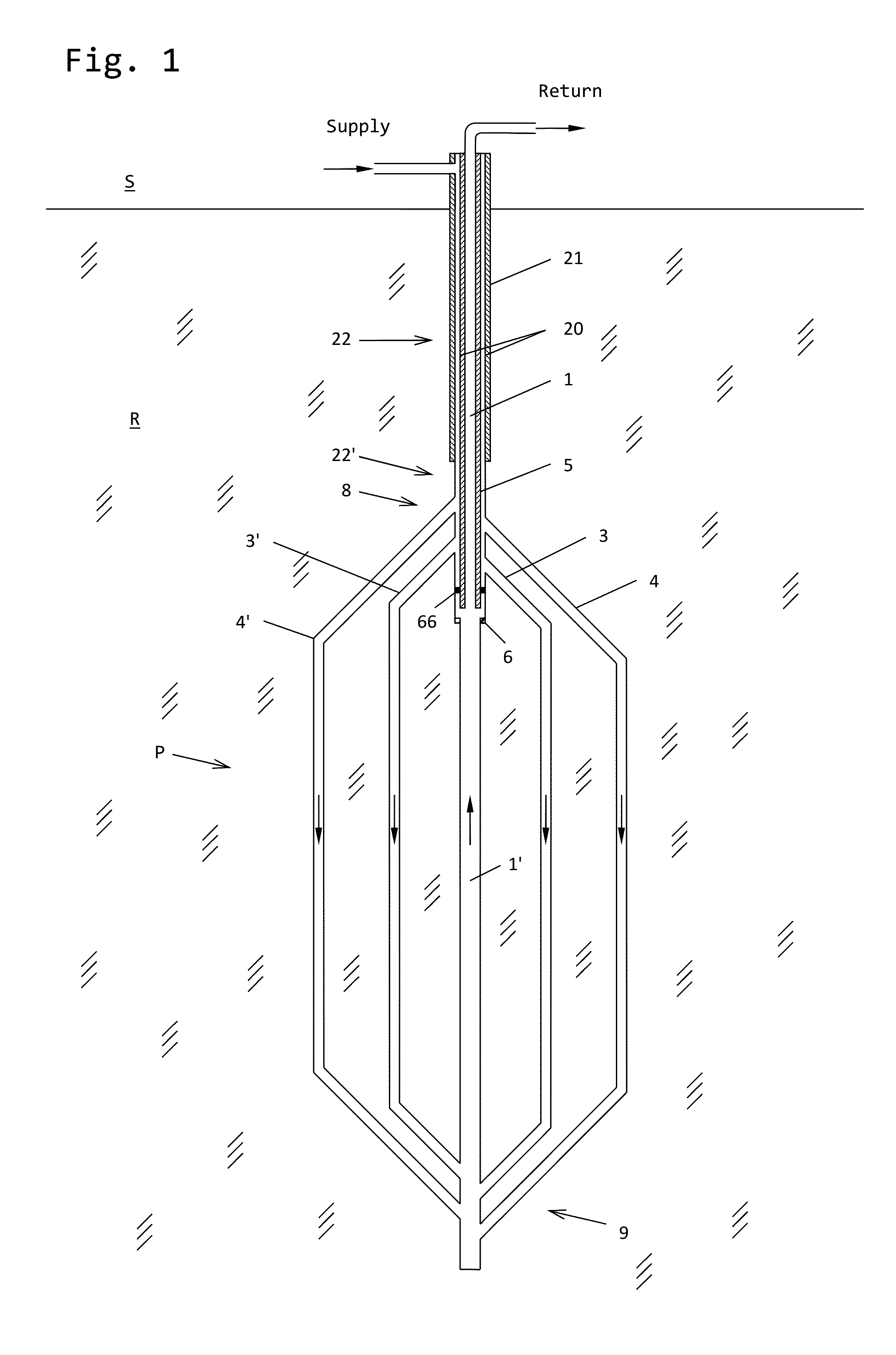
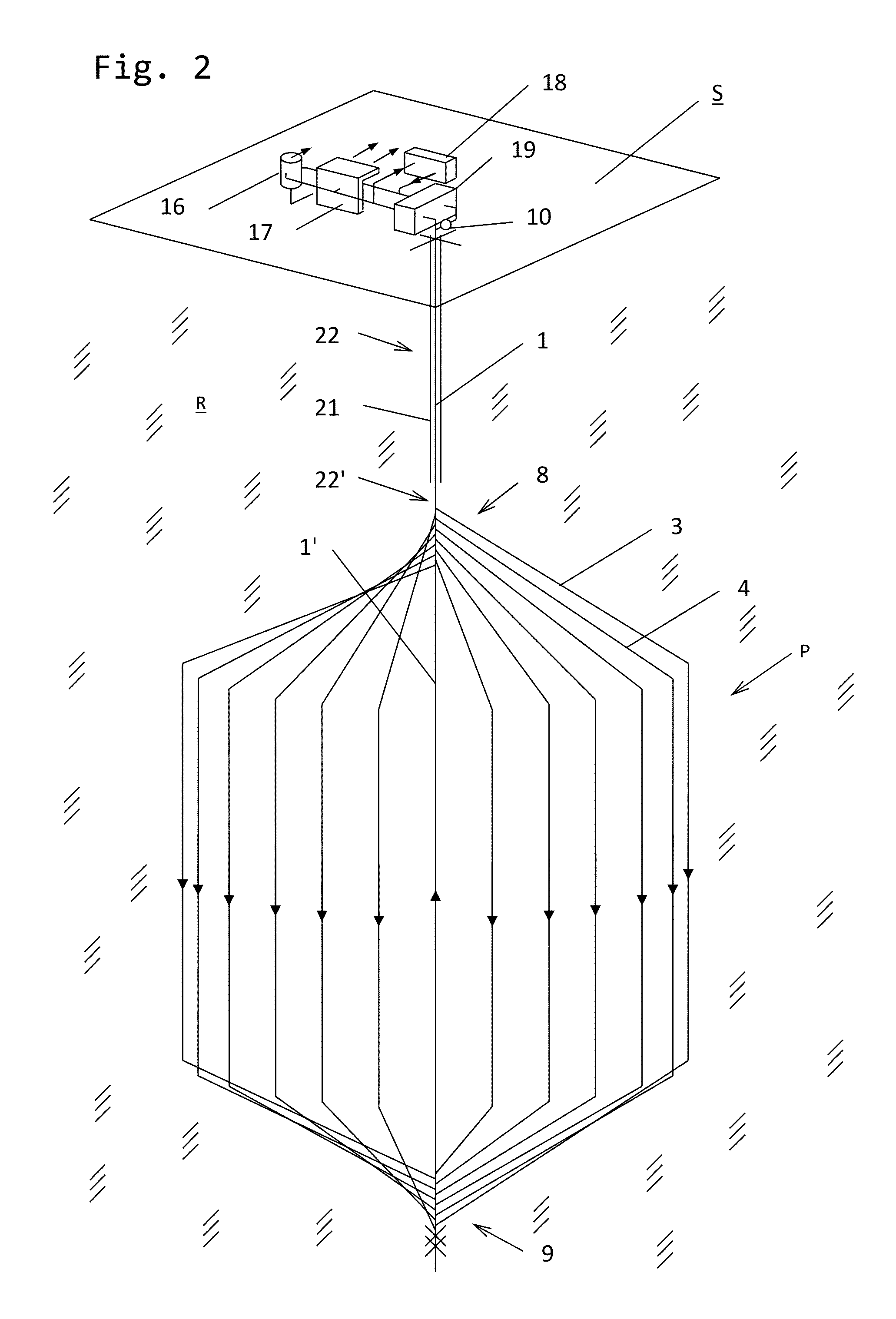
[0037]FIG. 26 illustrates the concept related to “horizontal” production holes, while FIG. 27 illustrates the concept related to “vertical” production holes. The main feature common to both concepts is the combined supply and return hole consisting of the borehole with an inner insulated pipe and a seal in the annular space separating the supply fluid flow from the return fluid flow. The insulated pipe can, for example, be a metal pipe with an outer layer of thermally insulating material or consist of only thermally insulating material. There exist various types of seals that can be used. The borehole is extended below the seal with the same or a smaller diameter hole forming a part of the return fluid flow. Casing in the upper part of the borehole is installed as required.

[0038]In FIG. 26 the production holes are drilled with an essential horizontal pattern near the bottom of the borehole giving the highest rock temperature and energy output per meter of production hole.

[0039]In FI...


PUM


Abstract

A plant for exploiting geothermal energy by circulating water or another fluid through a non-porous geological formation at a substantial depth below the earth surface, comprising multiple heat absorbing/production holes penetrating the said formation, with a total length of several kilometers and spaced more than 50 m apart. The production holes are connected to the surface by one single combined supply and return hole in which upward and downward flow is separated by a pipe comprising an insulating material and a seal. At the given positions of the common supply and return hole manifold zone designs connect the hole to the multiple production holes. The supply and return holes and production holes are closed circuits for transport of a fluid such as water through the said formation. A method for designing and establishing the plant is also disclosed.

Description


Claims


Application Information

Patent Timeline
Owner GEOVARME AS
Why Eureka
Try Eureka