
A driving shaft assembly of a screw drilling tool with a vibration damping function

A technology for screw drilling tools and transmission shafts, which is applied in the direction of rotation vibration suppression, driving devices for drilling in boreholes, drill pipes, etc., and can solve problems such as reducing the normal service life, falling accidents, loosening of screw drilling tool connections, etc., to achieve The effect of reducing drilling cost, reducing tripping and improving life

Active Publication Date: 2011-12-07
SOUTHWEST PETROLEUM UNIV
View PDF9 Cites 25 Cited by
  • Summary
  • Abstract
  • Description
  • Claims
  • Application Information

AI Technical Summary

Problems solved by technology

The existing screw drilling tools mainly bear the drilling pressure through the series bearings. The series bearings are in point-line contact, and they bear relatively large pressure and shear force during work. Under the action of impact load, their service life is greatly affected; while the universal The shaft is also greatly damaged by the impact, and the impact can easily cause damage to the petals and steel balls, which reduces the normal service life; the connecting buckles of the screw drilling tool are also prone to loosening and disconnection due to impact vibration, resulting in well-falling accidents
[0004] At present, there is no screw drilling tool designed with vibration damping parts, and the external special vibration damper usually greatly increases the length of the drill tool near the drill bit, affecting the steering ability of the directional drill or the lower BHA of the compound drill

Method used


Image

  • A driving shaft assembly of a screw drilling tool with a vibration damping function
  • A driving shaft assembly of a screw drilling tool with a vibration damping function
  • A driving shaft assembly of a screw drilling tool with a vibration damping function

Examples


Embodiment Construction

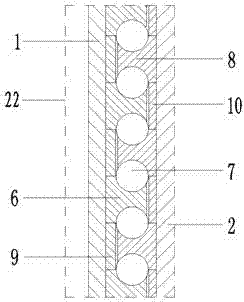
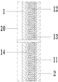
[0013] Such as figure 1 , figure 2 , image 3 with Figure 4 As shown, a screw drilling tool transmission shaft assembly with vibration damping function of the present invention is composed of a housing 1, an upper transmission shaft 2, an upper radial bearing static sleeve 3, an upper radial bearing movable sleeve 4, and a load bearing group 22 , vibration damping device 20, lower transmission shaft 15, lower short joint 16 and mandrel 18, etc., its structural features are: the upper transmission shaft 2 is installed inside the housing 1, and the lower end of the upper transmission shaft 2 has a spline groove 21; the upper diameter The outer wall and inner wall of the static bearing sleeve 3 cooperate with the inner wall of the housing 1 and the outer wall of the upper radial bearing movable sleeve 4 respectively, and the inner wall of the upper radial bearing movable sleeve 4 cooperates with the upper transmission shaft 2; the bearing bearing group 22 is installed on the ...


PUM


Abstract

The invention discloses a screw drill transmission shaft assembly which is used in oil and gas drilling and can reduce the drill vibration, prolong the service life of the drill and improve the mechanical drilling rate. The screw drill transmission shaft assembly consists of a shell, an upper transmission shaft, an upper radial bearing static sleeve, an upper radial bearing dynamic sleeve, a loadbearing group, a vibration reducing device, a lower transmission shaft, a lower short section, a central spindle and the like. The technical scheme is that: the upper transmission shaft is mounted inthe shell; the upper radial bearing static sleeve and the upper radial bearing dynamic sleeve are cooperatively mounted in an annular space formed by the shell and the upper transmission shaft; the load bearing group is mounted at the lower ends of the upper radial bearing static sleeve and the upper radial bearing dynamic sleeve; the vibration reducing device is mounted at the lower end of the load bearing group; when in work, a spline slot of the upper transmission shaft is matched with a spline of the lower transmission shaft; the lower short section is in threaded connection with the shell; and the central spindle is in threaded connection with the upper transmission shaft. The screw drill transmission shaft assembly disclosed by the invention does not increase the length of the lowerdrill, brings relatively little influence on the bottom drill combination, and can be applied to the angle building operation and curved borehole.

Description

technical field [0001] The invention relates to a driving shaft assembly of a screw drilling tool capable of reducing the vibration of a drilling tool used in oil and gas drilling, in particular to a driving shaft assembly of a screw drilling tool with a vibration damping function. Background technique [0002] During the drilling process, the screw drilling tool and the drill bit are drilled under a large drilling pressure, and the screw drilling tool outputs a large torque to drill, especially the roller cone bit drills by continuously crushing the rock with the teeth of the cone. The moment of breaking, the downhole drill string will produce longitudinal, lateral and torsional impact vibrations, especially when drilling hard formations or soft and hard interlayers. According to the field measurement, during the drilling process, the variation range of the WOB is generally ±35% to ±100% of the average WOB, and the maximum peak WOB can reach more than 3 times the average WO...

Claims


Application Information

Patent Timeline
Patent Type & Authority Applications(China)
IPC IPC(8): E21B4/00E21B17/00F16C41/00F16F15/10
Inventor 祝效华石昌帅李佳南童华
Owner SOUTHWEST PETROLEUM UNIV
Learn More