Horizontal ground-coupled heat exchanger for geothermal systems

a geothermal system and ground-coupled technology, applied in geothermal prediction/simulation, lighting and heating apparatus, heating types, etc., can solve the problems of reducing system efficiency, reducing efficiency, and reducing the cost of vertical systems, so as to reduce the length of required pipes and land area, reduce the major drawbacks of horizontal systems, and minimize the effect of large capacity

Inactive Publication Date: 2016-08-25
ENTIN VLADIMIR +2
View PDF3 Cites 3 Cited by
  • Summary
  • Abstract
  • Description
  • Claims
  • Application Information

AI Technical Summary

Benefits of technology

This patent proposes an innovation that allows for more efficient use of space by designing a vertical heat exchange system that can be placed horizontally or at different angles. By doing this, it reduces the amount of equipment needed and takes up less room than traditional methods. Additionally, the new system helps overcome common issues associated with Horizontal Exchangers such as being dependent upon seasonality and weather patterns. Overall, this technology offers improved efficiency and flexibility while reducing costs and limitations.

Problems solved by technology

The patent text describes a new system for geothermal heat exchangers that can be installed in horizontal or vertical configurations. The technical problem addressed in the text is the high cost and complexity of current vertical systems and the limitations of previous horizontal systems. The new system aims to decrease energy loss and improve performance in arid and semi-arid climate zones. The text describes the use of a pit thermally conductive exchanger for geothermal energy storage in a form of a pit with a uninsulated membrane and a direct charging system. The text also discusses the advantages and disadvantages of using horizontal exchangers for geothermal applications.

Method used


Image

  • Horizontal ground-coupled heat exchanger for geothermal systems
  • Horizontal ground-coupled heat exchanger for geothermal systems
  • Horizontal ground-coupled heat exchanger for geothermal systems

Examples


Embodiment Construction

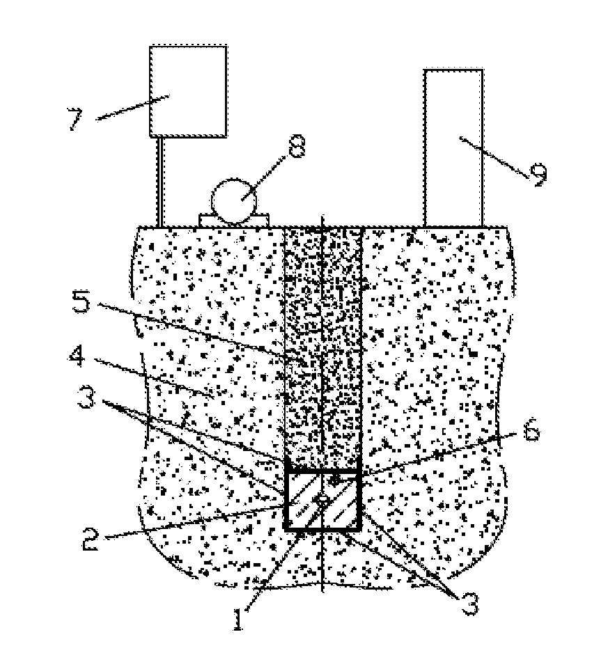
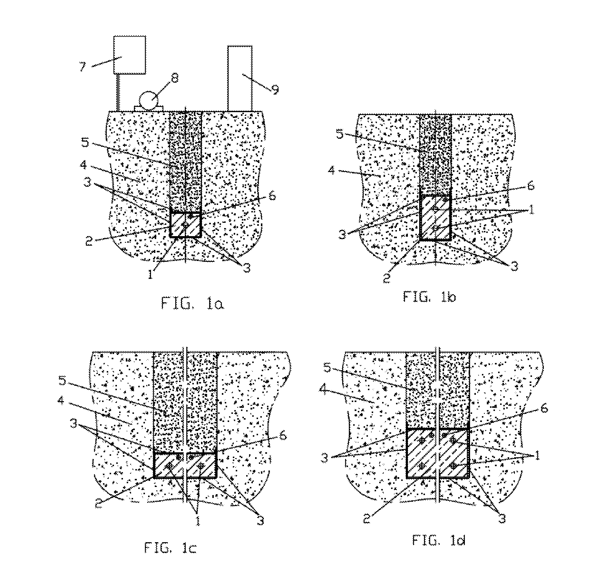
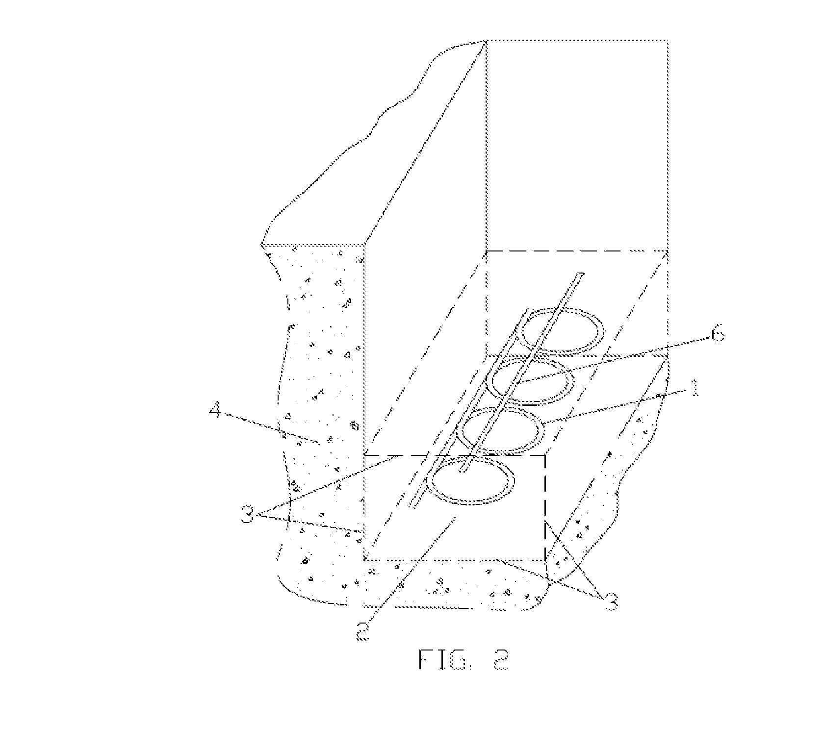
[0068]Some variants of principal schemes of the proposed horizontal closed-loop ground-coupled heat exchangers, containing one or number of pipes, are shown in FIGS. 1a, 1b, 1c, 1d. As a rule, in horizontal ground heat exchangers pipes are laid in trenches, dug in surrounding soil, but other laying also may be performed, that is not critical for the proposed invention. On FIGS. 1a, 1b, 1c, 1d the pipes 1 are laid in the stratum 2 with increased heat conductivity. The stratum is separated from all sides by thin waterproof material 3 from surrounding soil 4 and backfilling soil 5.

[0069]The FIGS. 1a, 1b, 1c, 1d show, as examples, some options for the pipes location: one straight pipe in the stratum (FIG. 1a), two straight pipes in the stratum in two levels (FIG. 1b), some number of pipes in the stratum in one level (FIG. 1c), some number of pipes in the stratum in two levels (FIG. 1d).

[0070]For controlling of water content and compensation for unintended small water leaks, the undergro...


PUM


Abstract

Horizontal ground-coupled heat exchanger for geothermal systems is proposed. The exchanger includes sub-surface formation of not expensive special structure heat conductive stratum around conduit loops. Analytical and finite element modeling allowed estimating the new structure efficiency. The proposed decision permits to increase by 2-3 times the transmitted heat power of the exchanger and correspondently to reduce the required pipe length and land area. The underground loop must be sized to meet the peak thermal power load. The proposed exchanger structure may fill simply this requirement, because at relatively short-term operation the efficiency of the proposed structure is even higher and reaches increasing by 2.5-4 times in dependence on climate zone.

Description


Claims


Application Information

Patent Timeline
Owner ENTIN VLADIMIR
Why Eureka
Try Eureka