
Horizontal ground-coupled heat exchanger for geothermal systems

a geothermal system and ground-coupled technology, applied in geothermal prediction/simulation, lighting and heating apparatus, heating types, etc., can solve the problems of reducing system efficiency, reducing efficiency, and reducing the cost of vertical systems, so as to reduce the length of required pipes and land area, reduce the major drawbacks of horizontal systems, and minimize the effect of large capacity

Inactive Publication Date: 2017-03-14
ENTIN VLADIMIR +2
View PDF15 Cites 1 Cited by
  • Summary
  • Abstract
  • Description
  • Claims
  • Application Information

AI Technical Summary

Benefits of technology

[0026]The aim of the proposed invention is creating of not expensive horizontal closed-loop ground-coupled exchanger with several times greater productivity and considerably reduced required pipes length and land area. The aim of the proposed invention also is development of system, which minimizes the major drawbacks of horizontal systems: dependence of productivity on climate, seasons, weather, rainfall, etc. and extends application of horizontal ground-coupled heal exchangers in arid and semi-arid regions, where now they are not applicable.
[0027]For realizing above mentioned aim—to reduce the area, occupied by the ground heat exchanger, pipes length and simultaneously to increase the energy transmission, the present invention proposes new closed-loop ground-coupled heat exchanging structures with additional stratum, which has increased thermal conductivity.
[0028]The proposed solutions are based on an idea of new structure of horizontal ground-coupled heat exchanger including formation of enlarged thermal conductivity stratum around pipes with the use of cheap available materials (sand, plastic film, water and others) and simple technology. Proposed exchanger is especially effective in arid and semi-arid climate zones.

Problems solved by technology

However, firstly, the described structure comprising two concentric cylinders with sand filling of gap between them and water entrance and flow through sand in outer cylinder and exit in the inner cylinder really is acceptable for vertical (not horizontal) exchangers only, secondly, water flow through sand due to significant hydraulic resistance requires spending considerable capacity that decreases the system efficiency.
However, vertical systems are considerably more expensive than horizontal geothermal heat exchangers.
Besides, vertical boreholes have depth 15-120 m with corresponding disadvantage of deep drillings, considerably complicated installation and maintenance.
Vertical drilling can provoke mixing between aquifers of different qualities and to be potential source of contamination.
It means that in this system there is no ability for effective using of geothermal energy.When impermeable member reaches the top of sump without the unidirectional water permeable layer, in addition to temperature instability there is necessity in too much quantity of water that can't be provided in arid and semiarid regions.
Such construction appears expensive and complicated.
Heat exchange with the Earth in this case means the loss of energy, which shortens the storage time of the previously stored heat energy.
Thus, frozen matrix due to “effect to insulate the frozen mass” principally cannot be used in geothermal systems.
But the main disadvantages of horizontal systems are larger land area required, dependence of performance on season, rainfall, drought potential (low groundwater levels), especially in sandy soils and elevated areas.

Method used


Image

  • Horizontal ground-coupled heat exchanger for geothermal systems
  • Horizontal ground-coupled heat exchanger for geothermal systems
  • Horizontal ground-coupled heat exchanger for geothermal systems

Examples


Embodiment Construction

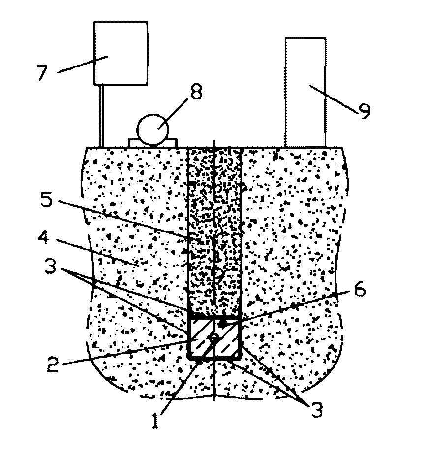
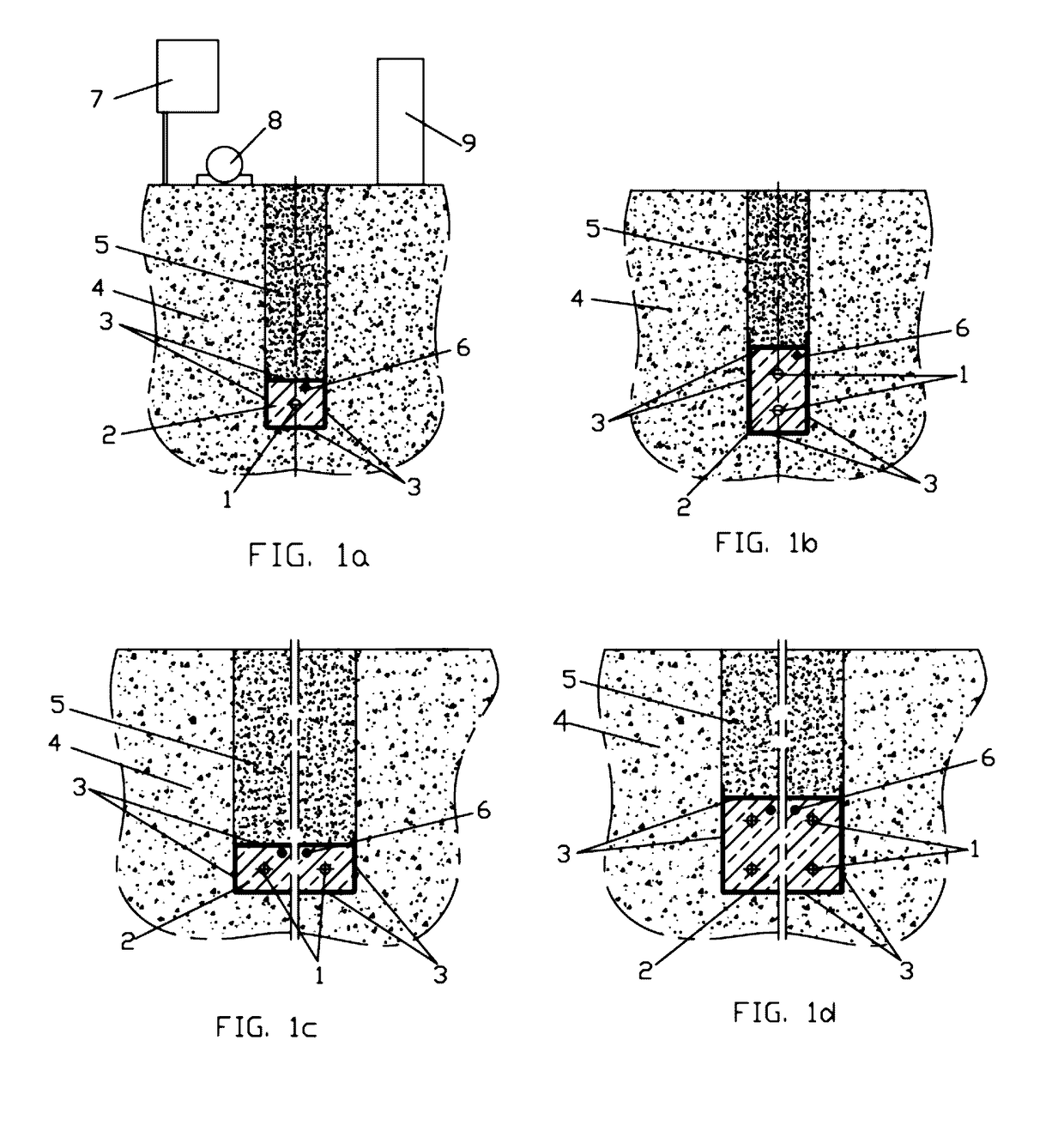
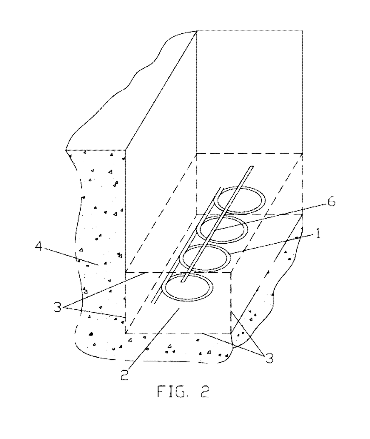
[0072]Some variants of principal schemes of the proposed horizontal closed-loop ground-coupled heat exchangers, containing one or number of pipes, are shown in FIGS. 1a, 1b, 1c, 1d. As a rule, in horizontal ground heat exchangers pipes are laid in trenches, dug in surrounding soil, but other laying also may be performed, that is not critical for the proposed invention. On FIGS. 1a, 1b, 1c, 1d the pipes 1 are laid in the stratum 2 with increased heat conductivity. The stratum is separated from all sides by thin waterproof material 3 from surrounding soil 4 and backfilling soil 5.

[0073]The FIGS. 1a, 1b, 1c, 1d show, as examples, some options for the pipes location: one straight pipe in the stratum (FIG. 1a), two straight pipes in the stratum in two levels (FIG. 1b), some number of pipes in the stratum in one level (FIG. 1c), some number of pipes in the stratum in two levels (FIG. 1d).

[0074]For controlling of water content and compensation for unintended small water leaks, the undergro...


PUM


Abstract

A horizontal ground-coupled heat exchanger for a geothermal system. The underground portion of the system includes; at least one conduit located in the soil below its frost line containing a heat transfer liquid; at least one stratum between the at least one conduit and the soil, totally disposed beneath the surface of the soil at a depth from the surface of the soil of 1.2-3 m and completely separated from the soil by at least two layers of a thin thermo-conductive waterproof material, the at least one stratum containing heat conductive water saturated fill material with the at least one conduit being disposed therein; and a means to compensate for small leaks of water from the at least one stratum. The size of the smallest dimension of the stratum per conduit is determined; the sizing is based on a user selected stratum efficiency parameter employing a relation provided herein.

Description

FIELD OF THE INVENTION[0001]The present invention relates to a field of geothermal heating / cooling systems for buildings, industry, agriculture, greenhouses, etc. In particular, the present invention describes structures of horizontal ground-coupled closed-loops heat exchanger with high effective heat energy transmitting with use of Earth source. Proposed structure considerably increases productivity of horizontal ground exchangers and decreases the required land area used for geothermal systems and makes minimal power dependence on drought, daily and seasonal variation of temperature and ground water level.BACKGROUND OF THE INVENTION[0002]Geothermal heating / cooling systems using heat ground source energy receive the worldwide application.[0003]The problems of enlargement of Earth source exchanger productivity by the way of increasing of heat transfer between ground and heat exchanger liquid are known. From the point of view of maximum heat transfer, vertical exchange geothermal sys...

Claims


Application Information

Patent Timeline
Patent Type & Authority Patents(United States)
IPC IPC(8): F24J3/08F24F5/00
CPCF24J3/082F24F2005/0057F24J2003/087F24T10/10F24T2201/00Y02B10/40Y02E10/10F24T10/13F24T2010/50
Inventor ENTIN, VLADIMIRKOMINAR, VLADIMIRLOKTEV, IRINA
Owner ENTIN VLADIMIR
Learn More