
Interactive projection system

a projection system and projection screen technology, applied in the field of interactive projection systems, can solve the problems of not being able to explore daylight or direct sunlight for display or entertainment systems, the use of interactive games or interfaces is limited to tvs, computer screens, and the use of direct sunlight has not yet been explored, so as to improve the immersive and location-based character of the game, increase the speed and precision of the spot, and be more challenging and fun to play

Active Publication Date: 2016-08-25
RGT UNIV OF MICHIGAN
View PDF4 Cites 8 Cited by
  • Summary
  • Abstract
  • Description
  • Claims
  • Application Information

AI Technical Summary

Benefits of technology

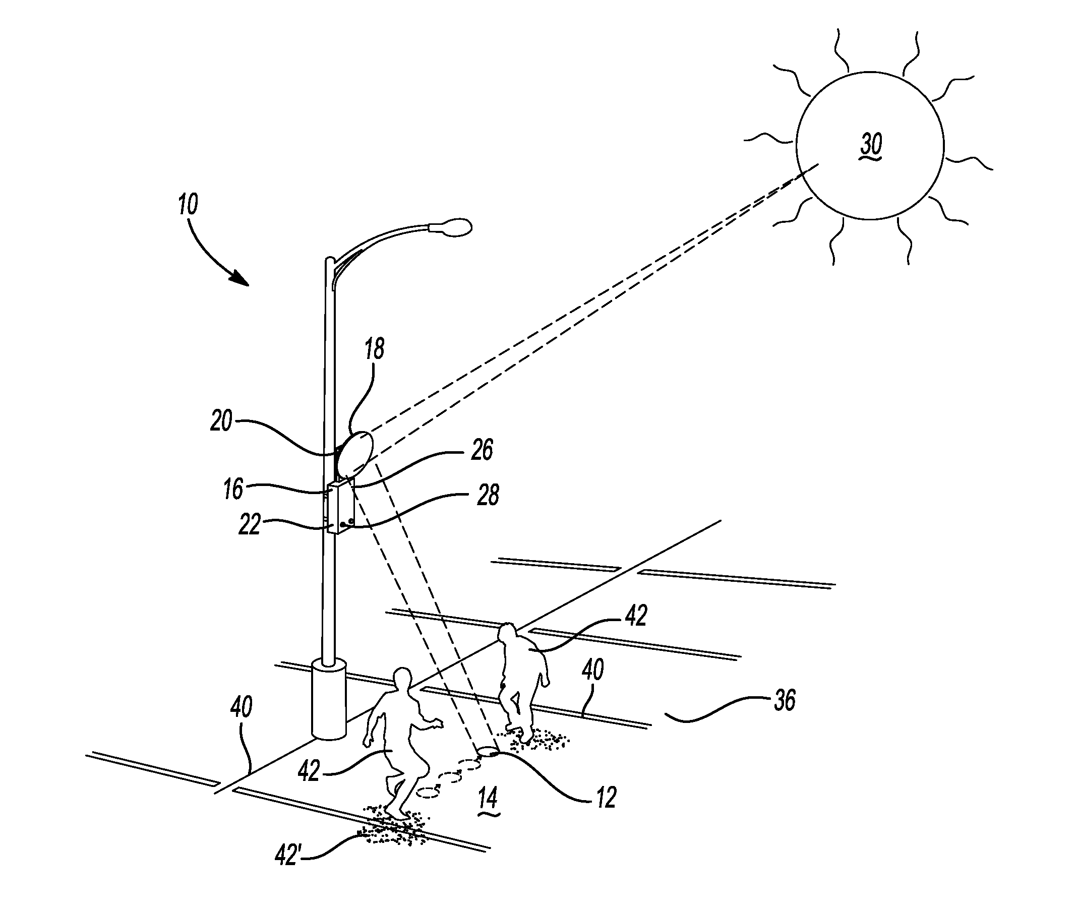
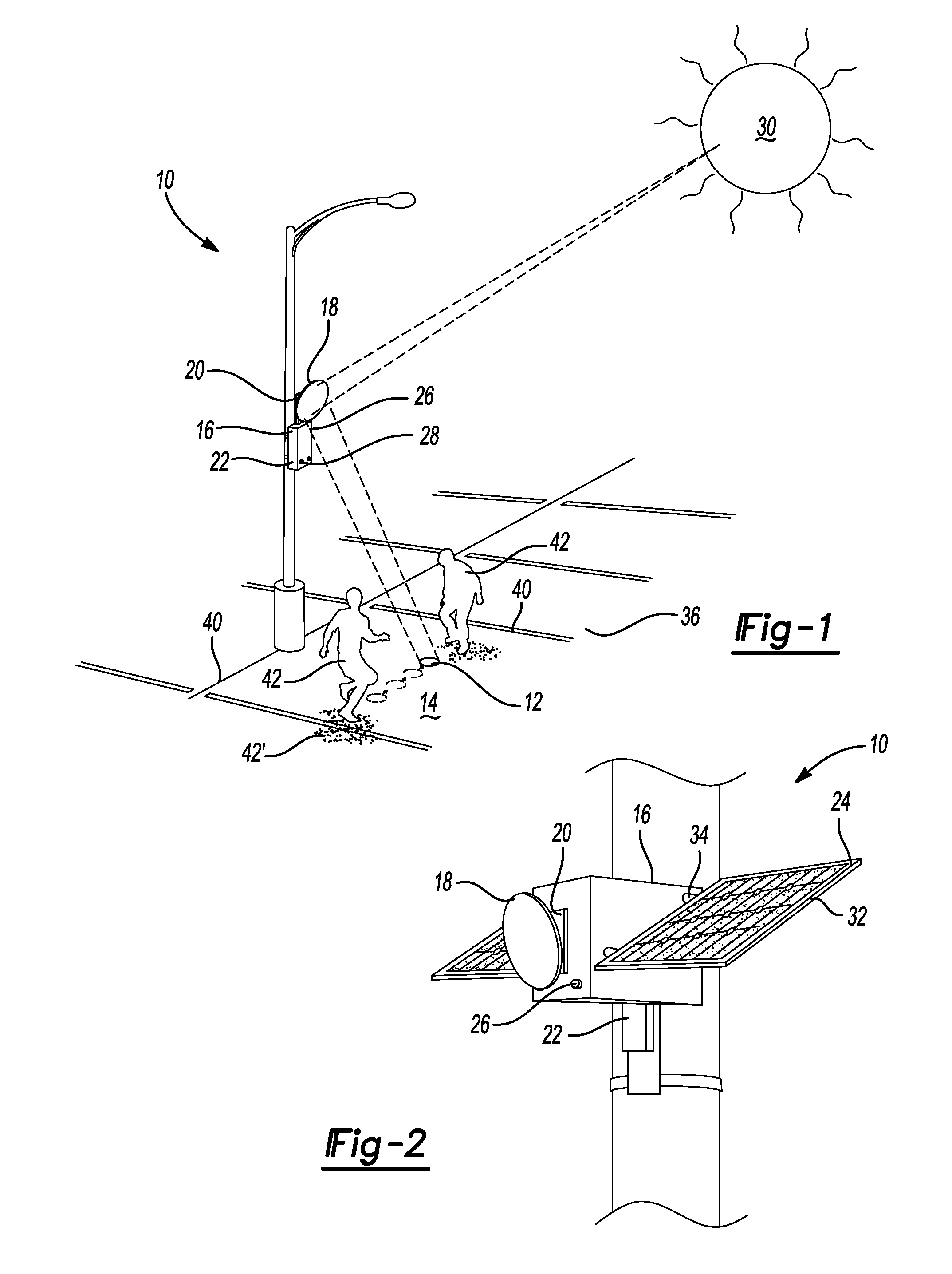
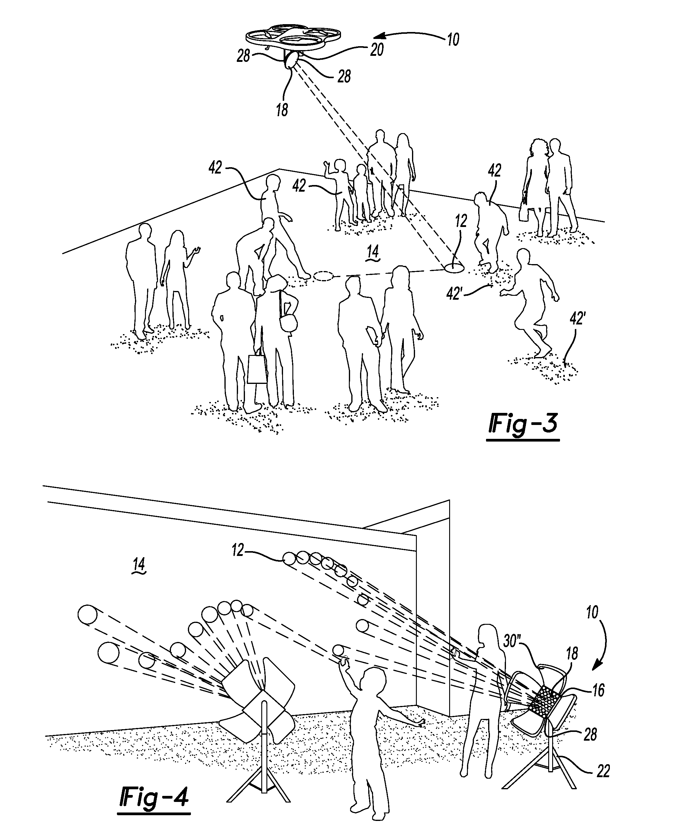
The present patent is for an interactive projection system that illuminates indicia onto a surface. The system can detect both stationary and movable features, and can move the illuminated indicia across the surface based on control system. The patent has found that players respond positively when the play field boundaries match the natural boundaries of the game location, making the game more immersive and location based. Additionally, increasing the speed and precision of the spot can make the game more challenging and interesting to play.

Problems solved by technology

Generally, interactive games or interfaces are limited to use on TV, computer screens, or conventional (digital video projections) and perform best in dimmed light conditions of a living room.
To date, daylight or direct sunlight has not yet been consequently explored for the use in display or entertainment systems.
In most video game applications, for example, direct sunlight interferes with, rather than supports, video displays and (motion-sensing) systems.
As a result, physical outdoor activities often conflict with video gaming activities.

Method used


Image

  • Interactive projection system
  • Interactive projection system
  • Interactive projection system

Examples


Embodiment Construction

[0016]Example embodiments will now be described more fully with reference to the accompanying drawings. Example embodiments are provided so that this disclosure will be thorough, and will fully convey the scope to those who are skilled in the art. Numerous specific details are set forth such as examples of specific components, devices, and methods, to provide a thorough understanding of embodiments of the present disclosure. It will be apparent to those skilled in the art that specific details need not be employed, that example embodiments may be embodied in many different forms and that neither should be construed to limit the scope of the disclosure. In some example embodiments, well-known processes, well-known device structures, and well-known technologies are not described in detail.

[0017]The terminology used herein is for the purpose of describing particular example embodiments only and is not intended to be limiting. As used herein, the singular forms “a,”“an,” and “the” may b...


PUM


Abstract

An interactive projection system for outputting illuminated indicia upon a projection surface. A detection system is operable to detect both stationary and movable features. A control system is operable to determine the position of the stationary and movable features. A reflective device reflects light from a light source (natural and / or artificial) upon the projection surface as the illuminated indicia. A drive system moves the reflective device, thereby moving the illuminated indicia across the projection surface in response to control system thereby simulating the stationary feature on the projection surface as a physical boundary to the illuminated indicia and simulating the movable feature contacting the illuminated indicia.

Description

CROSS-REFERENCE TO RELATED APPLICATIONS[0001]This application claims the benefit of U.S. Provisional Application No. 62 / 120,541, filed on Feb. 25, 2015. The entire disclosure of the above application is incorporated herein by reference.FIELD[0002]The present disclosure relates to an interactive projection system and, more particularly, relates to an interactive projection system employing sunlight and / or artificial light to produce static and / or dynamic images on indoor or outdoor surfaces that can be controlled by body and shadow movement, without the use of separate input devices or wearables.BACKGROUND AND SUMMARY[0003]This section provides background information related to the present disclosure which is not necessarily prior art. This section provides a general summary of the disclosure, and is not a comprehensive disclosure of its full scope or all of its features.[0004]Generally, interactive games or interfaces are limited to use on TV, computer screens, or conventional (digi...

Claims


Application Information

Patent Timeline
Patent Type & Authority Applications(United States)
IPC IPC(8): G02B19/00F21S9/03G09F19/18G02B26/08
CPCG02B19/0042G09F19/18F21S9/035G02B26/0816A63G31/00G02B19/0019G02B19/0023Y02B10/10
Inventor GRAF, ROLANDKWANMUANG, SURAT
Owner RGT UNIV OF MICHIGAN
Learn More