Multipath mitigation in positioning systems

Active Publication Date: 2016-09-01
SAMSUNG ELECTRONICS CO LTD
View PDF2 Cites 9 Cited by
  • Summary
  • Abstract
  • Description
  • Claims
  • Application Information

AI Technical Summary

Benefits of technology

[0034]According to the present invention, a method

Problems solved by technology

A common source of interference in conventional navigation systems is multipath interference, in which signals are reflected from object

Method used


Image

  • Multipath mitigation in positioning systems
  • Multipath mitigation in positioning systems
  • Multipath mitigation in positioning systems

Examples


Embodiment Construction

[0044]Embodiments of the present invention will now be described, by way of example only, with reference to the accompanying drawings.

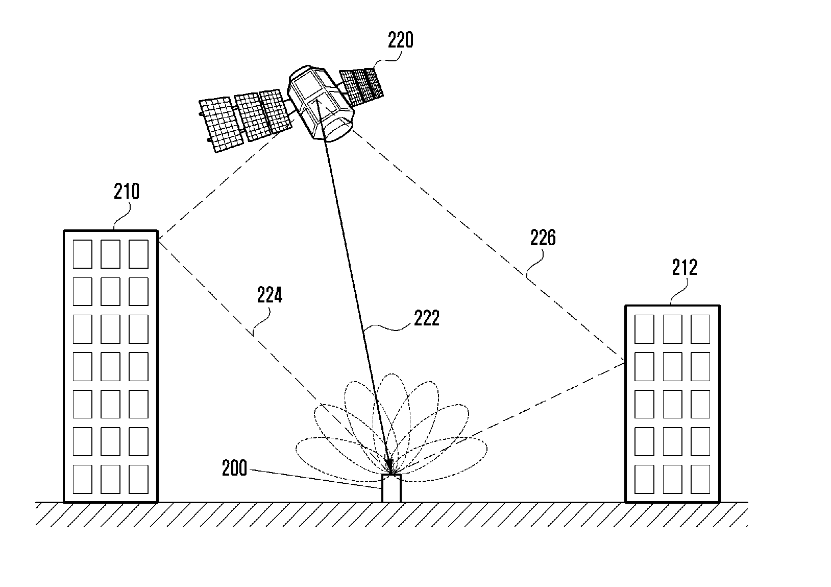
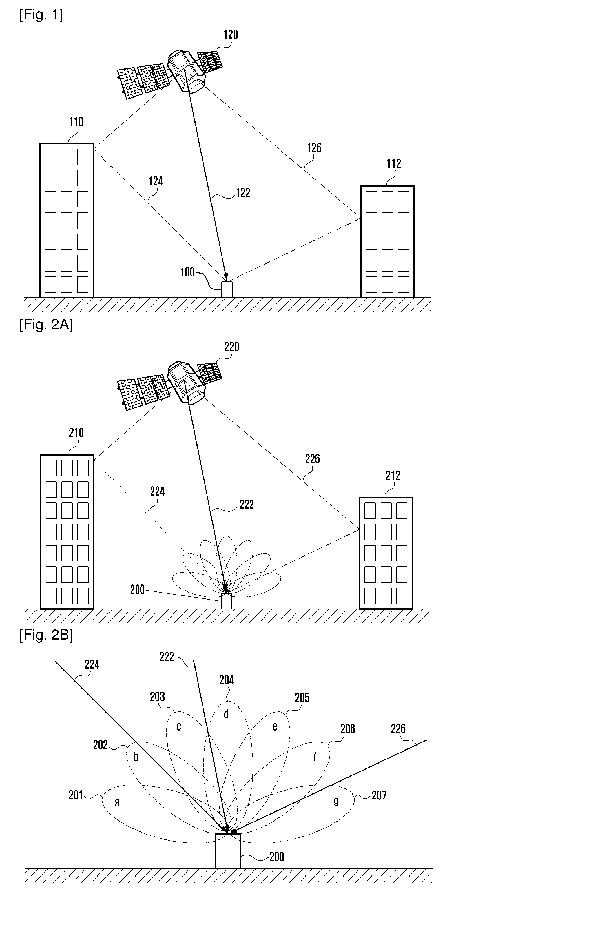
[0045]Referring now to FIG. 2A, a receiver for use in a satellite navigation system is illustrated, according to an embodiment of the present invention. The receiver 200 is configured to receive positioning signals formatted according to the Global Positioning System (GPS) standard, but in other embodiments a receiver may be configured for use with different navigation systems. The receiver 200 includes an antenna that is configured to have a directionality property, such that the receiver 200 can distinguish between signals received at different incident angles. In the present embodiment, the antenna is a single antenna configured to have a plurality of reception lobes, but in other embodiments an array of directional antennas may be used to provide a similar functionality. In FIG. 2A, the lobes of the antenna are illustrated using dotted lines.

[0046...


PUM


Abstract

An apparatus for receiving positioning signals comprises an antenna configured to output a plurality of antenna signals and a multipath compensation module for detecting multipath interference, and if multipath interference is detected, selecting one or more of the antenna signals and combining the selected one or more antenna signals to obtain a compensated signal. The antenna is arranged to distinguish between ones of the positioning signals received at different incident angles, and each antenna signal includes ones of the positioning signals received in a predetermined range of incident angles. The multipath compensation module may determine whether multipath interference is present in each antenna signal, and may not select any antenna signals which include interference when selecting the antenna signals to be combined. The gain of each antenna signal may be adjusted before the signals are combined, to maintain the noise power of each antenna signal below a predetermined limit. The phase of each antenna signal may be adjusted before the signals are combined, to reduce phase differences between the antenna signals.

Description

TECHNICAL FIELD[0001]The present invention relates to multipath mitigation in positioning systems. More particularly, the present invention relates to a receiver including an antenna configured to output a plurality of antenna signals corresponding to positioning signals received at different angles, a compensate signal being obtained by selecting one or more antenna signals and combining the selected antenna signals.BACKGROUND ART[0002]Satellite navigation systems are widely-used for determining the location of an earth-based receiver. The receiver calculates a distance, referred to as a “pseudorange”, to a satellite, based on a measured time-of-flight of a received signal and a known speed of the signal, i.e. the speed of light. Signals must be received from at least four satellites in order to perform triangulation and calculate a local clock offset at the receiver.[0003]A common source of interference in conventional navigation systems is multipath interference, in which signals...

Claims


Application Information

Patent Timeline
IPC IPC(8): G01S19/22G01S19/24
CPCG01S19/24G01S19/22
Inventor SURINDER, THIND
Owner SAMSUNG ELECTRONICS CO LTD
Why Eureka
Try Eureka