Liquid ejecting apparatus

a technology of liquid ejector and ejector, which is applied in the direction of printing, etc., can solve the problem of large amount of ink that is removed by wiping, and achieve the effect of discharging liquid

Inactive Publication Date: 2016-09-15
SEIKO EPSON CORP
View PDF25 Cites 6 Cited by
  • Summary
  • Abstract
  • Description
  • Claims
  • Application Information

AI Technical Summary

Benefits of technology

[0009]An advantage of some aspects of the invention is to provide a liquid ejecting apparatus capable of di

Problems solved by technology

However, this configuration has a problem that the ink received by a wiper support portion drips through the discharge port and soils an apparatus inner portion.
For

Method used


Image

  • Liquid ejecting apparatus
  • Liquid ejecting apparatus
  • Liquid ejecting apparatus

Examples


Embodiment Construction

[0037]Hereinafter, one embodiment of a liquid ejecting apparatus will be described with reference to the drawings.

[0038]The liquid ejecting apparatus is an ink jet printer that ejects ink (liquid) as an example of liquid onto a medium such as paper, for example, so as to perform printing on the medium.

[0039]In the individual drawings, an X direction is a movement direction of a wiper carriage, a Y direction is a transportation direction of the medium, and a Z direction is a direction orthogonal to the X direction and the Y direction.

Liquid Ejecting Apparatus

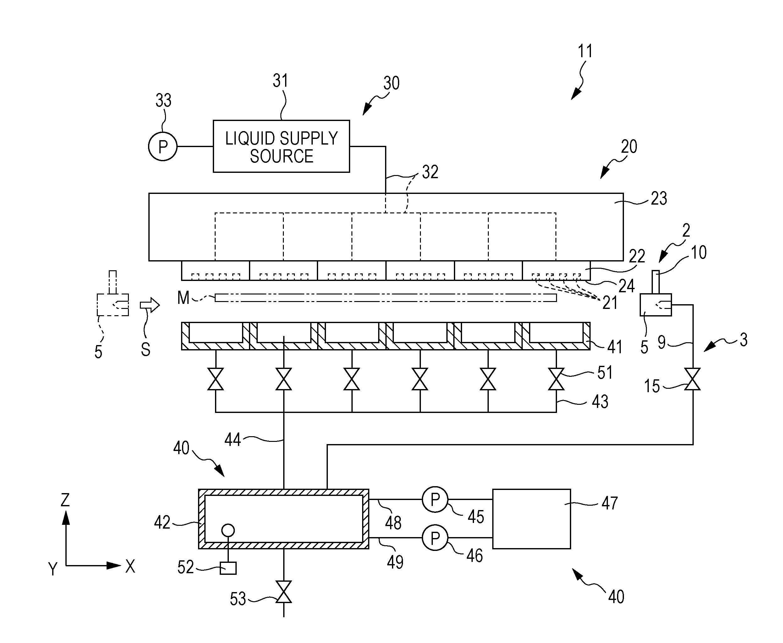
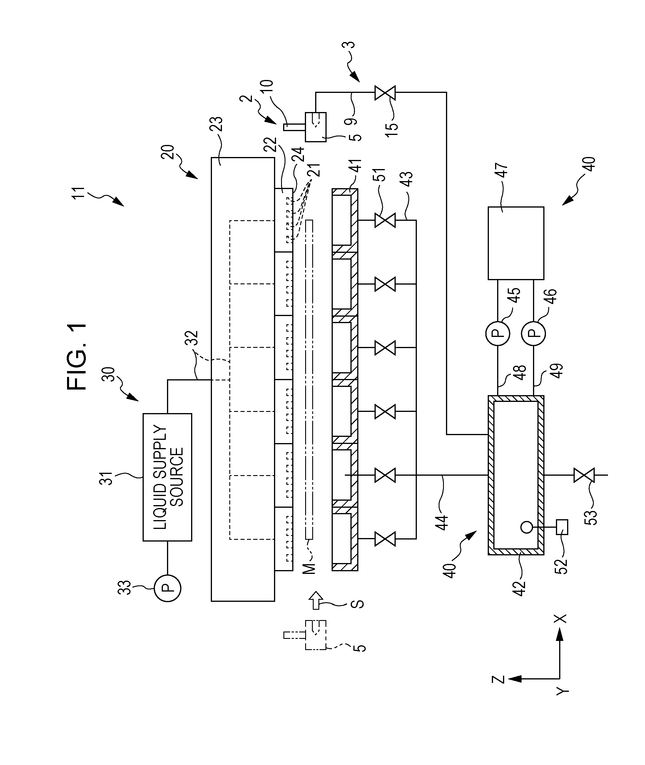
[0040]FIG. 1 is a view illustrating the schematic configuration of the liquid ejecting apparatus.

[0041]As illustrated in FIG. 1, a liquid ejecting apparatus 11 includes a liquid ejecting unit 20, a liquid supply unit 30, and a maintenance unit 40. The liquid ejecting unit 20 ejects ink (liquid) onto a medium M. The liquid supply unit 30 supplies the ink to the liquid ejecting unit 20. The maintenance unit 40 performs maintenance ...


PUM


Abstract

A liquid ejecting apparatus includes a liquid ejecting head having a nozzle which ejects a liquid onto a medium, a wiping member that wipes the liquid which has adhered to a nozzle forming surface of the liquid ejecting head, a support member that supports the wiping member, moves the wiping member relative to the liquid ejecting head, and has a receiving portion receiving the liquid wiped by the wiping member, and a connection flow path that is capable of being connected to the support member, wherein the receiving portion and the connection flow path communicate with each other with movement of the support member.

Description

BACKGROUND[0001]1. Technical Field[0002]The present invention relates to a liquid ejecting apparatus.[0003]2. Related Art[0004]In general, an ink jet printer that ejects ink (liquid) onto a recording medium such as paper through nozzles of openings formed on a nozzle forming surface of a liquid ejecting head for printing has been known as one type of a liquid ejecting apparatus. The printer normally includes a head maintenance device for maintaining ink ejection characteristics from the liquid ejecting head.[0005]Such head maintenance device has various functions.[0006]For example, the head maintenance device has a function of recovering the ink ejection characteristics through the nozzles by capping the nozzle forming surface of the liquid ejecting head by a suction cap and sucking thickened ink from the nozzles by a suction pump. Further, the head maintenance device has a function of wiping unnecessary ink that has adhered to the nozzle forming surface of the liquid ejecting head ...

Claims


Application Information

Patent Timeline
IPC IPC(8): B41J2/165
CPCB41J2/16535B41J2/16532B41J2/16508B41J2/16511B41J2/16538B41J2/16541B41J2/16544
Inventor KOBASHI, MASARUNAWANO, MASAHISASATO, KAZUHIKO
Owner SEIKO EPSON CORP
Why Eureka
Try Eureka