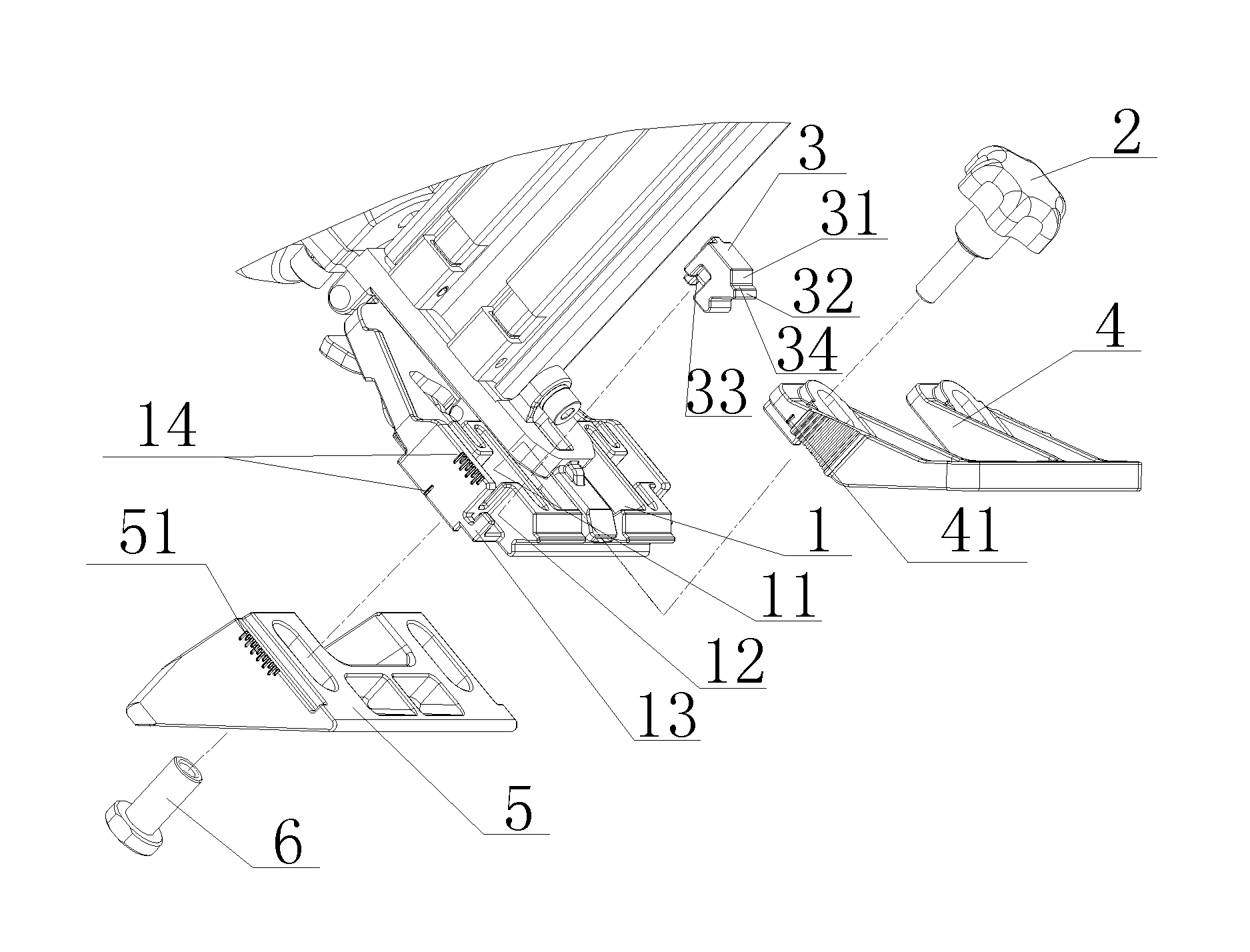
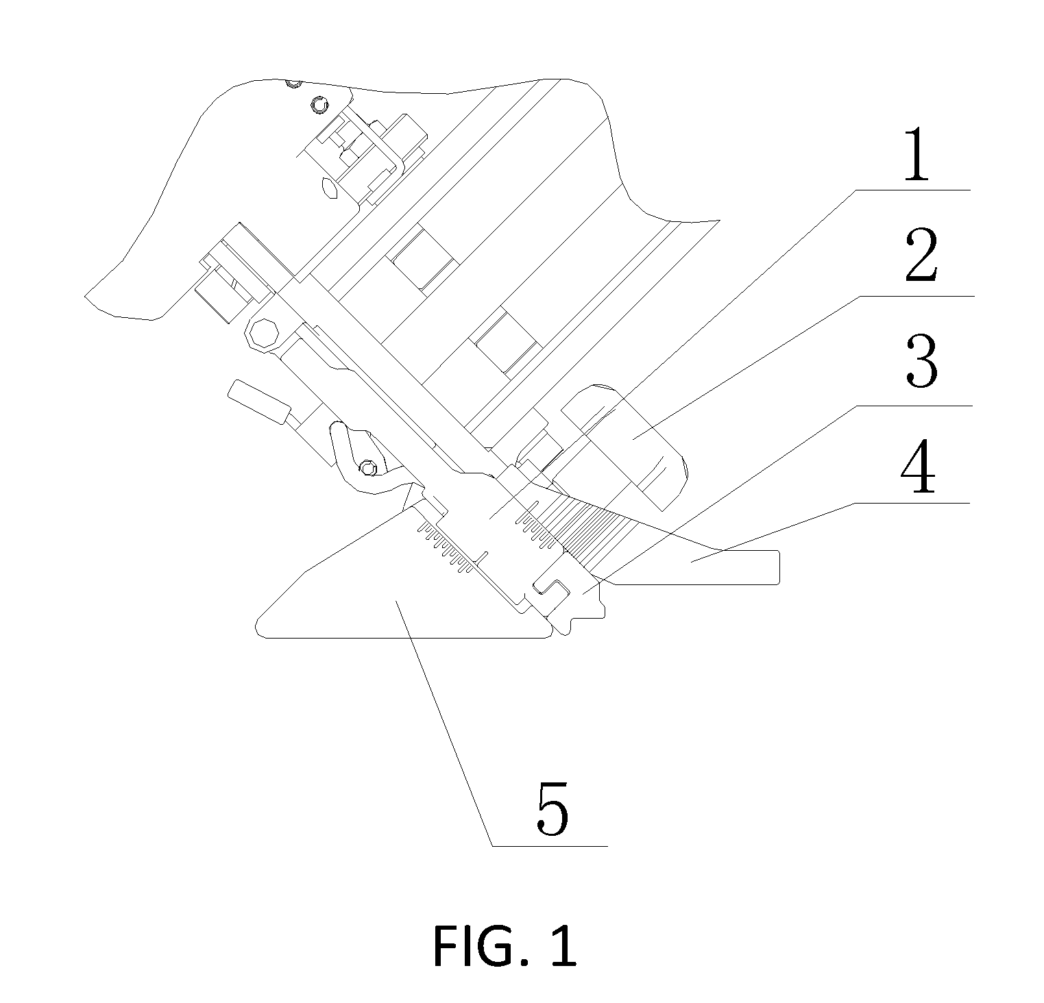
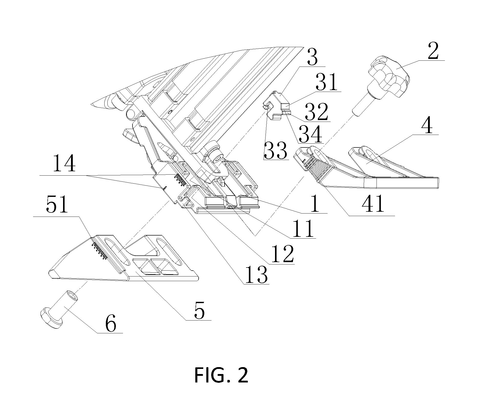
Floor nailing gun applicable to a floor having a lateral side with a recess structure or a protrusion structure

a technology of protruding structure and floor, applied in the field of nail guns, can solve the problems of severe restrictions on installation efficiency and unaddressed needs in the art, and achieve the effect of effective protecting edges and corners of the floor and enhancing product compatibility

Inactive Publication Date: 2016-09-22
TAIZHOU DAJIANG IND
View PDF1 Cites 2 Cited by
  • Summary
  • Abstract
  • Description
  • Claims
  • Application Information

AI Technical Summary

Benefits of technology

[0016]In one embodiment, the positioning block is provided with a groove that matches the protruding column so as to prevent movement of the positioning block.
[0017]According to the positioning structure of the floor nailing gun of the present invention, the positioning block is provided with at least two positioning surfaces. With this double positioning surface structure, when a floor having a lateral side with a protrusion structure is used, a corresponding positioning surface of the positioning block is set in a recessed state, thereby effectively protecting edges and corners of the floor while positioning. In addition, with the double positioning surface structure of the positioning block, the floor nailing gun can be applied to not only a floor having a lateral side with a recess structure, but also a floor having a lateral side with a protrusion structure, thereby enhancing the product compatibility.

Problems solved by technology

This limitation severely restricts the installation efficiency.
Therefore, heretofore unaddressed needs exist in the art to address the aforementioned deficiencies and inadequacies.

Method used


Image

  • Floor nailing gun applicable to a floor having a lateral side with a recess structure or a protrusion structure
  • Floor nailing gun applicable to a floor having a lateral side with a recess structure or a protrusion structure
  • Floor nailing gun applicable to a floor having a lateral side with a recess structure or a protrusion structure

Examples


Embodiment Construction

[0024]The present invention will now be described more fully hereinafter with reference to the accompanying drawings, in which exemplary embodiments of the invention are shown. This invention may, however, be embodied in many different forms and should not be construed as limited to the embodiments set forth herein. Rather, these embodiments are provided so that this disclosure will be thorough and complete, and will fully convey the scope of the invention to those skilled in the art. Like reference numerals refer to like elements throughout.

[0025]It will be understood that when an element is referred to as being “on” another element, it can be directly on the other element or intervening elements may be present therebetween. In contrast, when an element is referred to as being “directly on” another element, there are no intervening elements present. As used herein, the term “and / or” includes any and all combinations of one or more of the associated listed items.

[0026]It will be und...


PUM


Abstract

A floor nailing gun applicable to a floor having a lateral side with a recess structure or a protrusion structure includes a floor nailing gun main body that has a base plate for matching an upper surface of the floor, a supporting seat for matching the ground, and a positioning block used for matching the recess structure or the protrusion structure of the lateral side of the floor. The base plate and the supporting seat are respectively disposed on upper and lower sides of the floor nailing gun main body by a fastener. The positioning block is fastened between an end portion of the floor nailing gun main body such that the positioning block is positioned between the base plate and the supporting seat. The positioning block comprises at least two positioning surfaces.

Description

CROSS-REFERENCE TO RELATED APPLICATION[0001]This application claims the priority to Chinese Patent Application No. 201520157877.1, filed on Mar. 19, 2015, in the State Intellectual Property Office of P.R. China, which is hereby incorporated herein in its entirety by reference.FIELD OF THE INVENTION[0002]The present invention relates generally to nail guns, and more particularly, to a floor nailing gun applicable to a floor having a lateral side provided with a recess structure or a protrusion structure.BACKGROUND OF THE INVENTION[0003]The background description provided herein is for the purpose of generally presenting the context of the present invention. The subject matter discussed in the background of the invention section should not be assumed to be prior art merely as a result of its mention in the background of the invention section. Similarly, a problem mentioned in the background of the invention section or associated with the subject matter of the background of the inventi...

Claims


Application Information

Patent Timeline
Patent Type & Authority Applications(United States)
IPC IPC(8): B25C7/00
CPCB25C7/00
Inventor YANG, MING-JUNZHU, ZAI-JUNSHAO, SONG-SONG
Owner TAIZHOU DAJIANG IND
Why Eureka
Try Eureka