Substrate for controlling movement direction of animal cells, and cell identification method and cell separation method using the same

a technology of animal cells and substrates, which is applied in the field of substrates for controlling the movement direction of animal cells, and cell identification methods and cell separation methods using the same. it can solve the disadvantage of chemotaxis

Active Publication Date: 2016-09-22
JAPAN SCI & TECH CORP
View PDF9 Cites 1 Cited by
  • Summary
  • Abstract
  • Description
  • Claims
  • Application Information

AI Technical Summary

Problems solved by technology

However, in the method of separating cells using chemotaxis, there is a risk in which, since cells are stimulated with a chemical substance or a growth factor, properties of cells such as differentiation, proliferation, and functional expression of target cells are influenced, and the properties of cells before and after stimulation may be changed.
That is, since chemotaxis tends to destabilize properties of the target cells, use of chemotaxis is disadvantageous in a cell therapy or diagnosis in which stimulated cells are administered into a living body.

Method used


Image

  • Substrate for controlling movement direction of animal cells, and cell identification method and cell separation method using the same
  • Substrate for controlling movement direction of animal cells, and cell identification method and cell separation method using the same
  • Substrate for controlling movement direction of animal cells, and cell identification method and cell separation method using the same

Examples


example 1

(1) Manufacture of a Substrate Having a Three-Dimensional Pattern

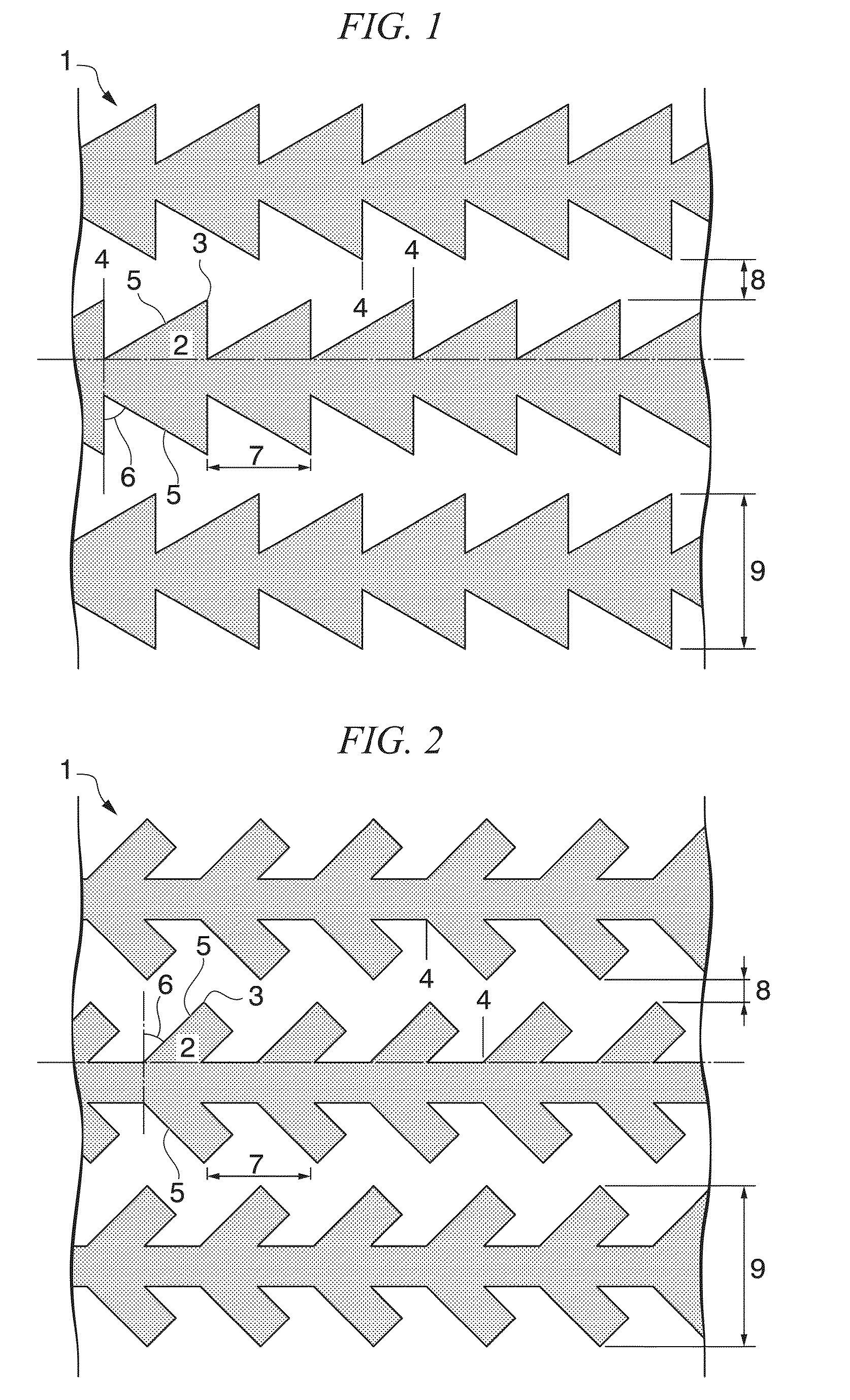
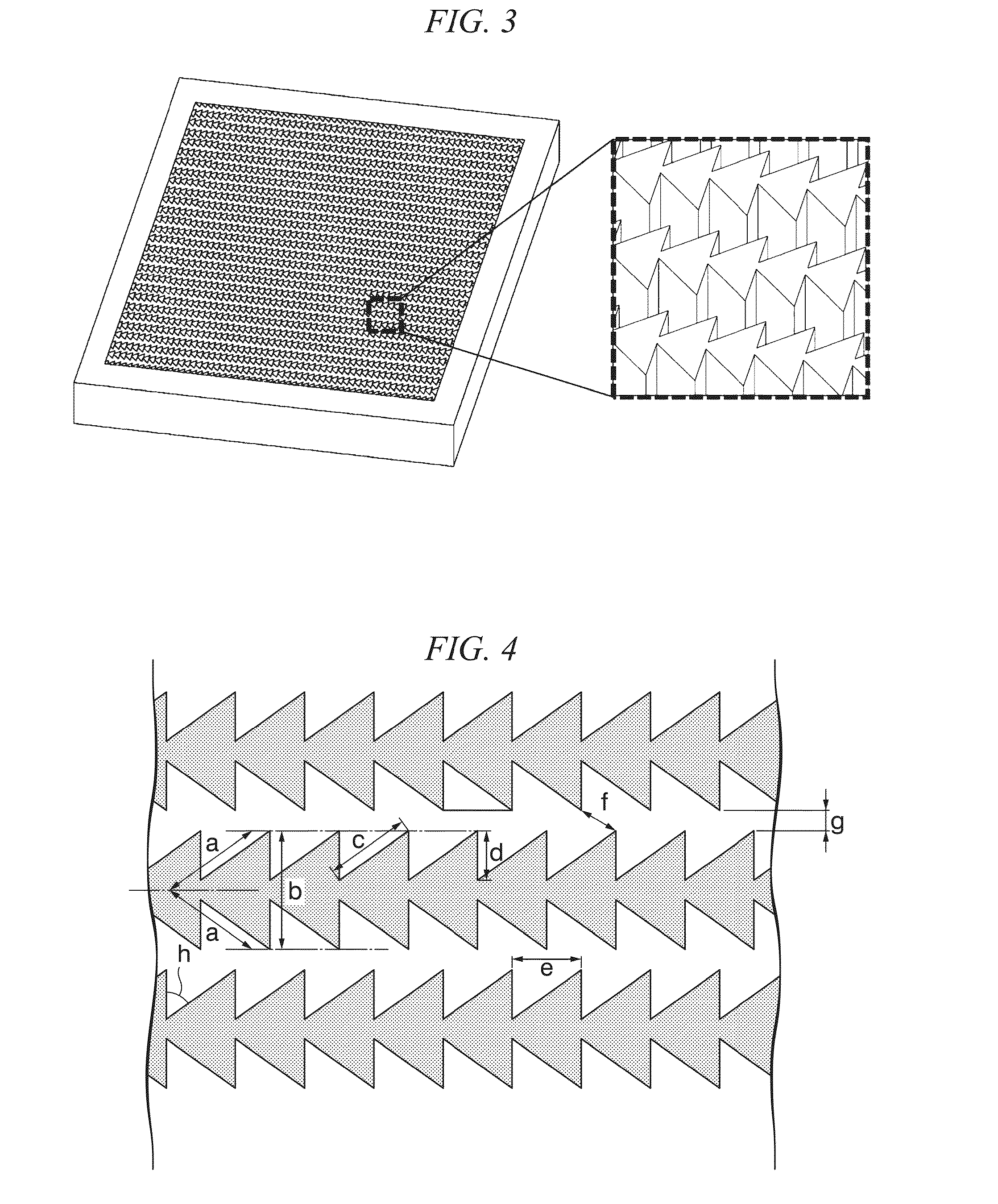
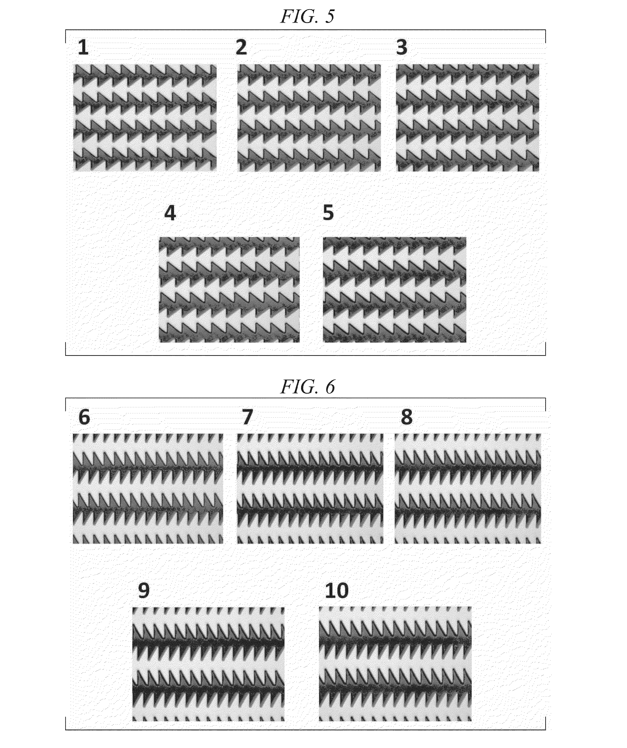
[0074]With respect to areas of quartz photomasks (commercially available from MITANI MICRONICS Co., Ltd.) having 25 areas (squares of 1 mm), photomasks that have a basic structure shown in FIG. 4 and have 15 types of patterns 1 to 15 in which portion dimensions and angles indicated by a to h are different were prepared.

[0075]On a silicon substrate (10 mm×10 mm) having a thermally oxidized film of 900 nm, hexamethyldisilazane (MMDS, commercially available from TOKYO OHKA KOGYO Co., Ltd.) and a resist composition (OFPR-5000LB, commercially available from TOKYO OHKA KOGYO Co., Ltd.) were spin-coated (1000 rpm for 5 seconds to 4000 rpm for 45 seconds). After a prebake was performed (110° C. for 2 minutes), the previously prepared quartz photomasks and the silicon substrate coated with a resist film were inserted into an exposure device (MA-20, commercially available from MIKASA Co., Ltd.) and exposed for 1.5 seconds.

[0076]...

example 2

[0081](1) PKH26 Staining of NIH3T3 cells

[0082]The substrates manufactured in Example 1(2) were immersed at a bottom of the 35 mm cell culture dish to which the DMEM medium was added and degassed at −0.09 Mpa for one minute while lightly shaking, and after the culture medium was replaced, immersed in the culture medium and left for 12 hours without change. The NIH3T3 cells were seeded at 1×10⁴ cells / cm2 in the dish containing the substrate having a three-dimensional pattern, cultured for 2 hours, and then immersed in PKH26 (500-fold dilution, commercially available from Sigma-Aldrich Co. LLC) for 4 minutes at room temperature. A reaction of PKH26 was stopped by FBS, and then washing was performed with the culture medium. A time from when the NIH3T3 cells were stained with PKH26 until the washing operation was completed was about 0.25 hours. Such procedures were modified and used with reference to a staining protocol of PKH26.

[0083]The substrates to which the NIH3T3 cells stained with...


PUM

PropertyMeasurementUnit
heightaaaaaaaaaa
distanceaaaaaaaaaa
heightaaaaaaaaaa

Abstract

The present invention provides a control substrate for controlling a movement direction of animal cells. The control substrate for controlling a movement direction of animal cells has a surface which includes a plurality of grooves, the grooves are formed from a bottom between opposing walls and the opposing walls forming the grooves wherein the walls include a plurality of columnar protrusions. Vertex parts of the columnar protrusion are formed to face between vertex parts of two columnar protrusions formed in the opposing wall and such vertex parts face the same direction.

Description

TECHNICAL FIELD[0001]The present invention relates to a substrate for controlling a movement direction of animal cells, and a method of identifying cells and a method of separating cells using the substrate, which can identify or separate cells using a difference of moving capabilities between cells.[0002]Priority is claimed on Japanese Patent Application No. 2013-229898, filed Nov. 6, 2013, the content of which is incorporated herein by reference.BACKGROUND ART[0003]Cells in movable environments such as blood, a lymphatic fluid or a liquid culture medium have characteristics in which they move (migrate) in response to a chemical stimulus which are caused by a chemical substance, a growth factor or the like. Cells also migrate in response to an electrical stimulus, a physical stimulus such as a contact stimulus, or other external factors in such environments. Research and development have been conducted on methods, a device, an instrument and a material used for the method, wherein ...

Claims


Application Information

Patent Timeline
Patent Type & Authority Applications(United States)
IPC IPC(8): G01N33/483
CPCG01N33/4833G01N33/5005C12N5/0068C12N2535/00C12M47/04
Inventor SUNAMI, HIROSHIYOKOTA, IKUKO
Owner JAPAN SCI & TECH CORP
Why Eureka
Try Eureka