Method and medical imaging system for compensating for image artifacts in medical imaging

Active Publication Date: 2016-09-22
SIEMENS HEALTHCARE GMBH
View PDF3 Cites 1 Cited by
  • Summary
  • Abstract
  • Description
  • Claims
  • Application Information

AI Technical Summary

Benefits of technology

The invention aims to minimize image errors in medical imaging devices caused by limited field of view and partially protruding body parts.

Problems solved by technology

Preferably, however, this is not possible outside of the imaging zone or the field of view under normal usage conditions.

Method used


Image

  • Method and medical imaging system for compensating for image artifacts in medical imaging
  • Method and medical imaging system for compensating for image artifacts in medical imaging

Examples


Embodiment Construction

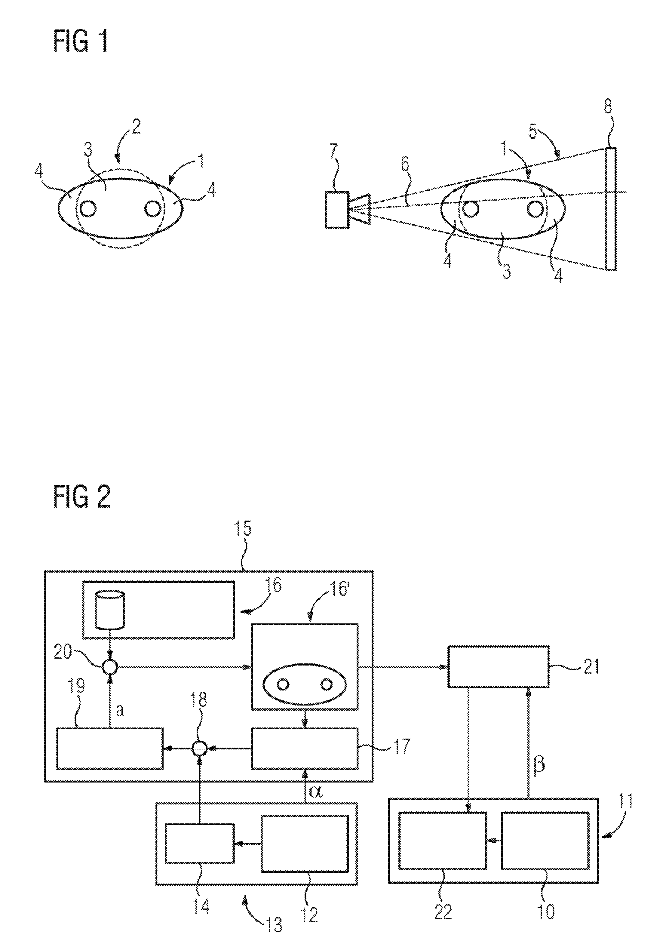
[0029]Referring now to the figures of the drawings in detail and first, particularly to FIG. 1 thereof, there is shown a juxtaposition of a first and a second field of view. Illustrated in the diagram on the left in this case is a body 1 that is to be examined, part of which is located in a first field of view 2. As depicted here, the body 1 has a first subregion 3, which is located in the first field of view 2, and two second subregions 4, which in the present example are located outside of the first field of view 2. The two second subregions 4 nonetheless have an effect on measurements in the first field of view 2 and as a result are responsible for undesirable image artifacts that are caused by the second subregion 4 being disposed outside of the first field of view 2. The image artifacts are typically referred to as “wrap-around artifacts” or “truncation artifacts”. The first field of view 2 can have a circular shape, for example. This can be the case, for example, for a magneti...


PUM


Abstract

A method compensates for image artifacts in a first imaging device for imaging a first subregion of a body. The image artifacts are caused by a second subregion of the body being disposed outside of a first field of view for the first device. First measured data for the first field of view is acquired by the first device. The first subregion lies in the first field of view. Second measured data are acquired for a second field of view in a second imaging device. Image data representing the subregions in the second device are calculated from the second measured data. A model representing the subregions is calibrated using the calculated image data. The data representing the second subregion in the first device are simulated using a calibrated model. A correction of the first measured data is performed using simulated data for reducing the image artifacts.

Description

CROSS-REFERENCE TO RELATED APPLICATION[0001]This application claims the priority, under 35 U.S.C. §119, of German patent application DE 10 2015 204 718.0, filed Mar. 16, 2015; the prior application is herewith incorporated by reference in its entirety.BACKGROUND OF THE INVENTIONField of the Invention[0002]The invention relates to a method for compensating for image artifacts in a medical imaging device for imaging a first subregion of a body. The image artifacts are caused by a second subregion of the body that is to be imaged, which second subregion is disposed outside of a predetermined field of view for the medical imaging device. The invention also relates to a medical imaging system containing two medical imaging devices by which such a method can be carried out.[0003]Generally, the different established medical imaging devices or modalities can perform imaging only in a limited field of view. Depending on the respective device and the size of a body or an object of which at le...

Claims


Application Information

Patent Timeline
IPC IPC(8): G06T11/00
CPCG06T2211/40G06T11/005G06T11/008G06T2211/432
Inventor ERTEL, DIRKKYRIAKOU, YIANNIS
Owner SIEMENS HEALTHCARE GMBH
Why Eureka
Try Eureka