
Depth-enhanced tomosynthesis reconstruction

Active Publication Date: 2019-04-18
KONINKLJIJKE PHILIPS NV
View PDF11 Cites 3 Cited by
  • Summary
  • Abstract
  • Description
  • Claims
  • Application Information

AI Technical Summary

Benefits of technology

The proposed method and system described in this patent improves the resolution of tomographic angle imaging by using prior knowledge of the structure being observed. This helps to reduce image artifacts and increase the contrast-to-noise ratio of the underlying structure. Overall, this technique helps to make tomographic angle imaging more accurate and reliable.

Problems solved by technology

Tomosynthesis enables limited-angle tomographic imaging with good “in-plane” (that is, orthogonal to a central projection direction), but poor depth resolution.
The relatively small tomographic angle results in blurring of structures, which appear as “out-of-plane” (that is, in depth direction along the central projection direction) artifacts in neighboring slices.
Diagnostically relevant structures such as lesions are well defined (or “delineated”) in-plane but are in general difficult (if at all) to be delineated through-plane.

Method used


Image

  • Depth-enhanced tomosynthesis reconstruction
  • Depth-enhanced tomosynthesis reconstruction
  • Depth-enhanced tomosynthesis reconstruction

Examples


Embodiment Construction

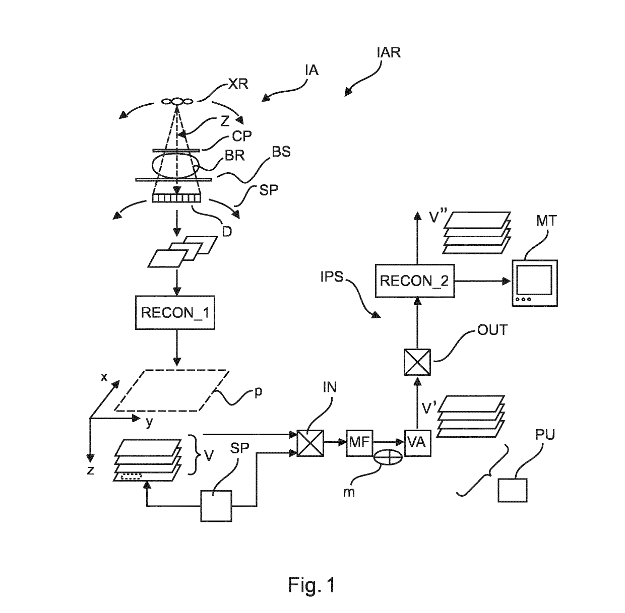
[0050]With reference to FIG. 1, there is shown a schematic block diagram of an x-ray based imaging arrangement IA.

[0051]The imaging arrangement IA comprises an x-ray imaging apparatus IA such as mammography imaging equipment. The imaging arrangement further comprises an image processing system IPS broadly configured to process imagery generated by the imaging apparatus IA.

[0052]The x-ray imaging apparatus IA comprises an X-ray source XR and an X-ray sensitive detector D. The x-ray source XR is configured to emit x-ray radiation that passes in a beam through an examination or imaging region and is then incident on an x-ray sensitive surface of the detector D. The detector D is in particular a digital detector such as a flat panel detector or a line detector or other. In the imaging region between the x-ray source and the detector there is a recess portion with a breast support BS and a compression plate CP.

[0053]The object BR to be imaged, such as the human breast, resides during ima...


PUM


Abstract

An Image processing system (IPS) and related method and imaging arrangement (IAR). The system (IPS) comprises an input interface (IN) for receiving i) a 3D input image volume (V) previously reconstructed from projection images (π) of an imaged object (BR) acquired along different projection directions and ii) a specification of an image structure in the input volume (V). A model former (MF) of the system (IPS) is configured to form, based on said specification, a 3D model (m) for said structure in the input 3D image volume. A volume adaptor (VA) of the system (IPS) is configured to adapt, based on said 3D model (m), the input image volume to so form a 3D output image volume (V′).

Description

FIELD OF THE INVENTION[0001]The present invention relates to an image processing system, image processing method, to an imaging arrangement, to a computer program element and to a computer readable medium.BACKGROUND OF THE INVENTION[0002]Tomosynthesis enables limited-angle tomographic imaging with good “in-plane” (that is, orthogonal to a central projection direction), but poor depth resolution. The relatively small tomographic angle results in blurring of structures, which appear as “out-of-plane” (that is, in depth direction along the central projection direction) artifacts in neighboring slices. Diagnostically relevant structures such as lesions are well defined (or “delineated”) in-plane but are in general difficult (if at all) to be delineated through-plane.[0003]Moreover, due to the limited-tomographic angle problem, there typically exist several solutions, which are all consistent with the measured projection data. In other words, an iterative tomosynthetic reconstruction alg...

Claims


Application Information

Patent Timeline
IPC IPC(8): G06T11/00
CPCG06T11/008G06T2211/424G06T2211/436
Inventor ERHARD, KLAUS
Owner KONINKLJIJKE PHILIPS NV
Learn More