
Method for encoding and decoding images, device for encoding and decoding images and corresponding computer programs

a technology of encoding and decoding images, applied in the field of image processing, can solve the problems of high bit rate, disturbance of signal transmitted to the decoder, damage to video compression efficiency, etc., and achieve the effect of easy and accurate selection of coefficients, high disturbance, and increased compression performance levels of coders

Active Publication Date: 2016-09-22
ORANGE SA (FR)
View PDF0 Cites 4 Cited by
  • Summary
  • Abstract
  • Description
  • Claims
  • Application Information

AI Technical Summary

Benefits of technology

The patent text describes a method for predicting the sign of residual data in video compression. By considering the current block prediction mode, the method can identify which residual data is most predictable and can minimize discontinuities at the borders of the blocks. This results in better compression performance and, ultimately, a better quality of reconstruction of the image on the decoder. The method also allows for accurate selection of coefficients with the most predictable sign, without causing high disturbances in the signal. As a result, the compression performance levels of the coder are increased while the signaling cost is reduced effectively.

Problems solved by technology

Given the many information items to be signaled in the stream, the result thereof is that the systematic addition of a sign bit into the stream to be transmitted to the decoder is costly in terms of bit rate and detrimental to the signal compression performance levels.
However, the coefficient for which the sign is predicted does not necessarily result from an optimum choice, such that the sign prediction applied is likely to result in disturbances in the signal transmitted to the decoder.
Such disturbances inevitably damage the video compression efficiency.

Method used


Image

  • Method for encoding and decoding images, device for encoding and decoding images and corresponding computer programs
  • Method for encoding and decoding images, device for encoding and decoding images and corresponding computer programs
  • Method for encoding and decoding images, device for encoding and decoding images and corresponding computer programs

Examples


Embodiment Construction

Detailed Description of the Coding Part

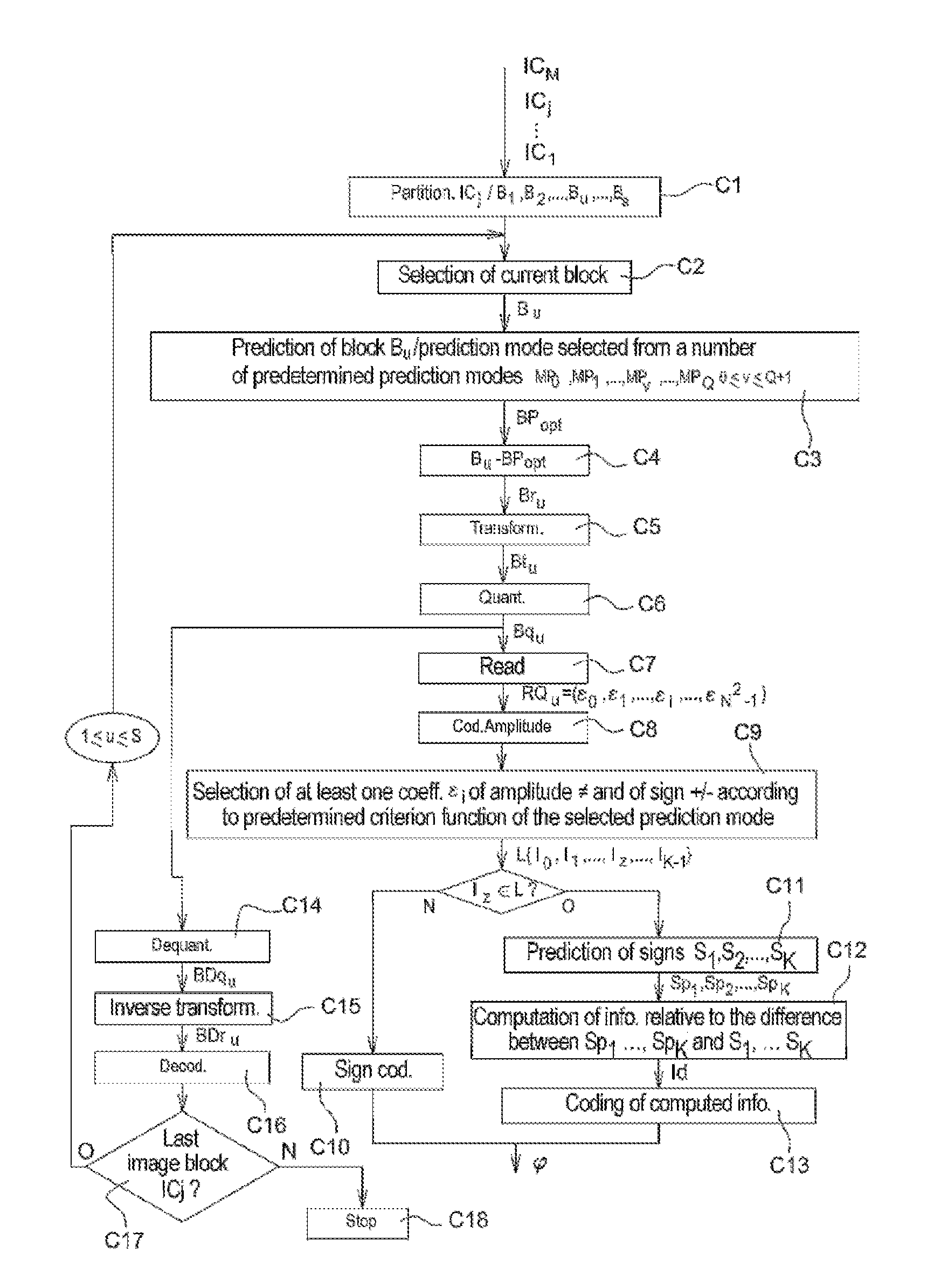
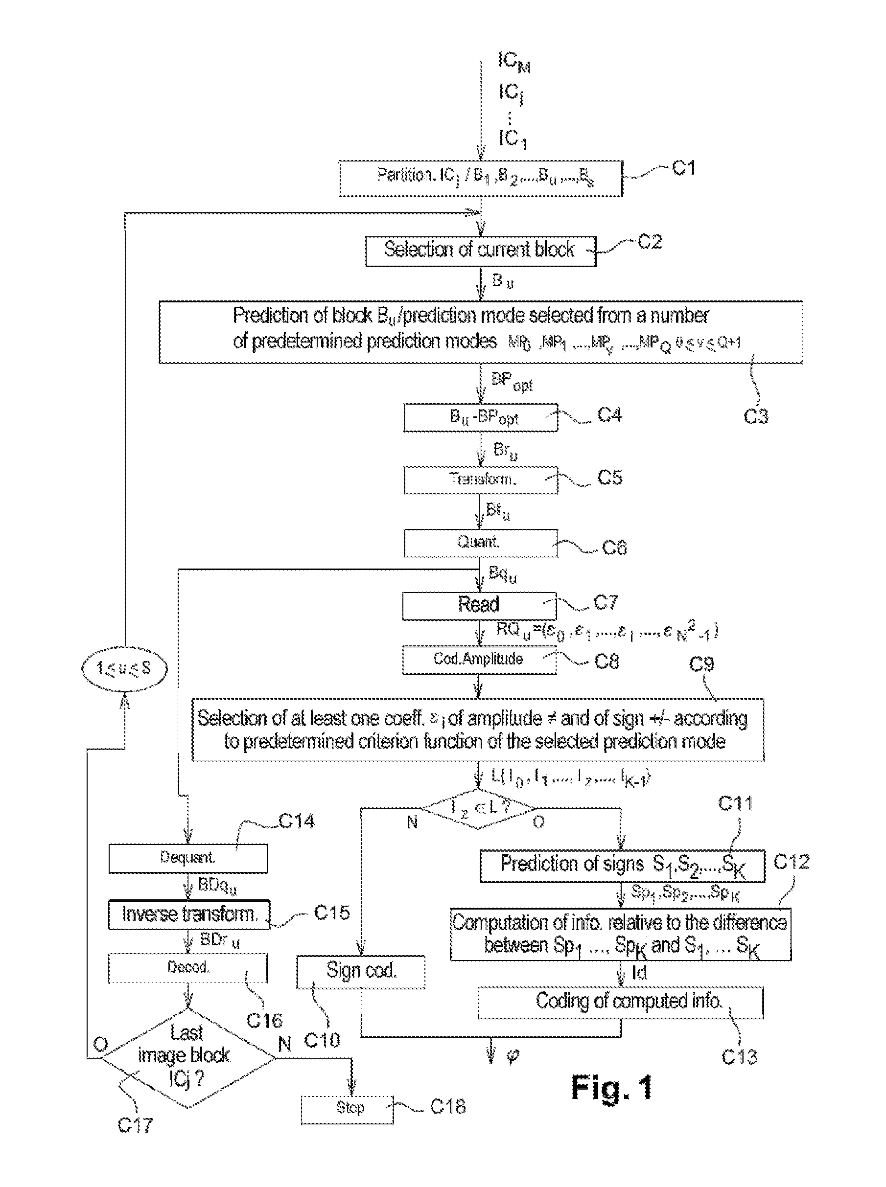
[0092]An embodiment of the invention will now be described, in which the coding method according to the invention is used to code an image or a sequence of images according to a binary stream close to that that is obtained by a coding in accordance, for example, with the HEVC standard.

[0093]In this embodiment, the coding method according to the invention is for example implemented in a software or hardware manner by modifications to a coder initially conforming to the HEVC standard. The coding method according to the invention is represented in the form of an algorithm comprising steps C1 to C18 as represented in FIG. 1.

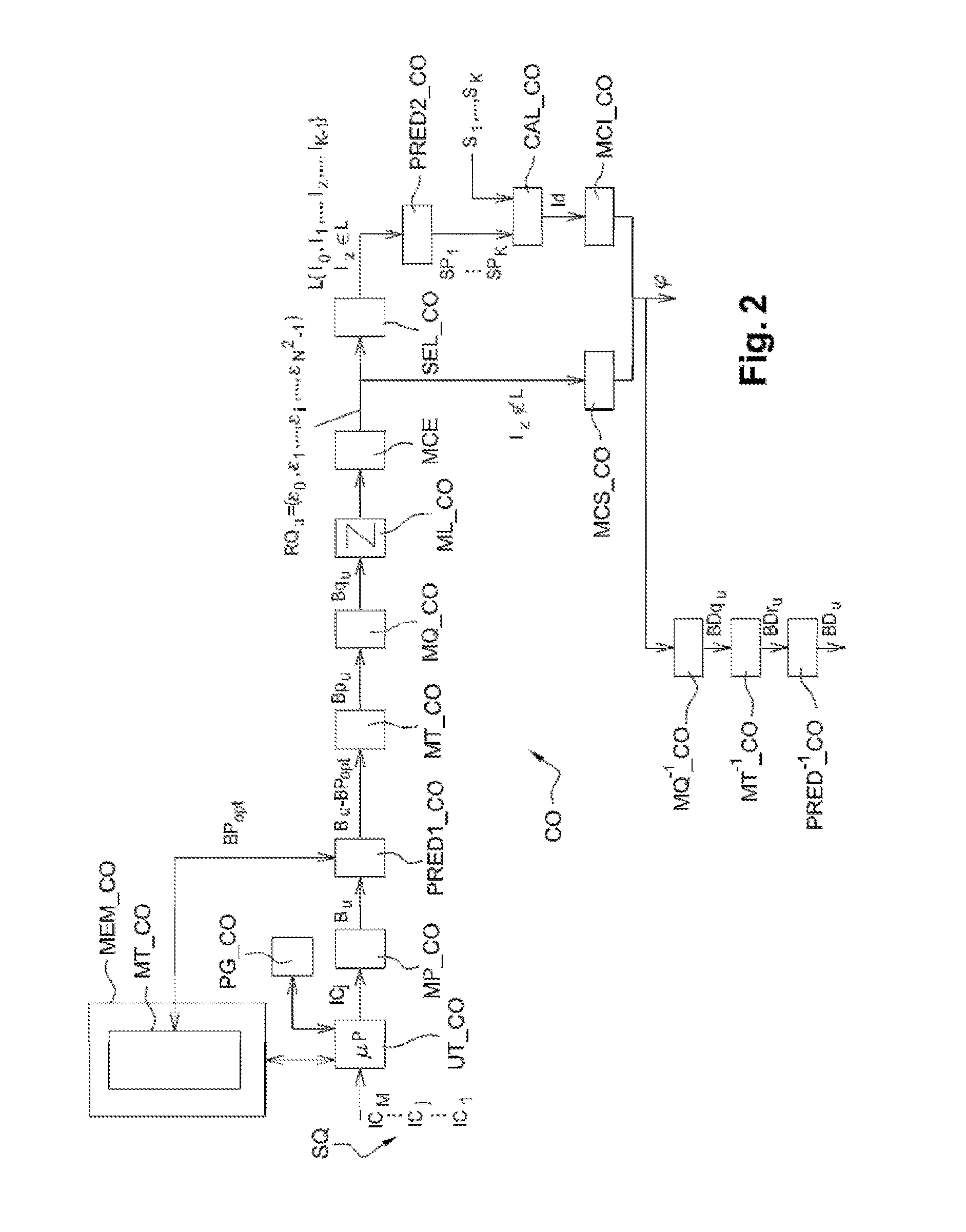
[0094]According to the embodiment of the invention, the coding method according to the invention is implemented in a coding device CO represented in FIG. 2.

[0095]As illustrated in FIG. 2, such a coding device comprises a memory MEM_CO comprising a buffer memory MT_CO, a processing unit UT_CO equipped for example with a microproc...


PUM


Abstract

A method is providing for encoding at least one image cut into blocks. The method implements, for a current block to be encoded, acts of: predicting the current block in accordance with a prediction mode selected among predetermined prediction modes; obtaining a predictor block; determining a residual data set, representative of the difference between the predictor block obtained and the current block, the residual data being likely to have an amplitude and a sign; selecting, from the residual data set, a piece of residual data assigned an amplitude and a sign, using a predetermined criterion which is a function of the selected prediction mode; obtaining a predicted value of the sign of the selected piece of residual data; calculating information representing the difference between the predicted value of the sign and the value of the sign of the selected piece of residual data; and encoding the calculated information.

Description

CROSS-REFERENCE TO RELATED APPLICATIONS[0001]This application is a Section 371 National Stage Application of International Application No. PCT / FR2014 / 052673, filed Oct. 21, 2014, the content of which is incorporated herein by reference in its entirety, and published as WO 2015 / 059400 on Apr. 30, 2015, not in English.FIELD OF THE INVENTION[0002]The present invention relates generally to the field of image processing, and more specifically to the coding and decoding of digital images and of digital image sequences.[0003]The coding / decoding of digital images applies notably to images from at least one video sequence comprising:[0004]images from a same camera and following one another in time (coding / decoding of 2D type),[0005]images from different cameras oriented according to different views (coding / decoding of 3D type),[0006]corresponding texture and depth components (coding / decoding of 3D type),[0007]etc. . . .[0008]The present invention applies similarly to the coding / decoding of i...

Claims


Application Information

Patent Timeline
Patent Type & Authority Applications(United States)
IPC IPC(8): H04N19/119H04N19/157H04N19/176
CPCH04N19/119H04N19/157H04N19/176H04N19/102H04N19/18H04N19/184H04N19/463
Inventor HENRY, FELIX
Owner ORANGE SA (FR)
Learn More