
Pneumatic tire

a technology of pneumatic tires and conductive parts, applied in the field of pneumatic tires, can solve the problems of reducing productivity and uniformity, complication of manufacturing steps, and radio noises, and achieve the effects of reducing the range, and reducing the cost of production

Active Publication Date: 2016-09-29
TOYO TIRE & RUBBER CO LTD
View PDF2 Cites 8 Cited by
  • Summary
  • Abstract
  • Description
  • Claims
  • Application Information

AI Technical Summary

Benefits of technology

The design achieves stable electrical conduction performance, improves uniformity, and maintains productivity by preventing covered states and ensuring balanced lateral rigidity, thus addressing the limitations of existing tire technologies.

Problems solved by technology

As a result, problems like radio noises tend to occur.
However, in the tire, since the conductive route is formed via the belt layer, it can not correspond to the case that a topping rubber of the belt layer is formed by a non-conductive rubber.
However, since the conductive portion formed as an L-shaped cross sectional form as mentioned above is formed such a shape as to be one-sided in the tire width direction, there has been found that it causes a reduction of productivity and a deterioration of uniformity.
In other words, in order to make a profile of the tread rubber symmetrical in the tire having the conductive portion mentioned above, there is generated such a necessity that a thickness of a cap portion is differentiated between left and right sides by taking a thickness of the conductive portion into consideration, thereby causing a complication of a manufacturing step, and further a reduction of a productivity.
Further, since a rigidity of the tread rubber is different between a side in which the conductive portion is provided and a side in which it is not provided, uniformity in a lateral direction of the tire tends to be deteriorated, and especially a lateral force variation (LFV) tends to become large.
The tire which is manufactured while remaining in the covered state cannot achieve an electrical conduction performance in the early stage of a wear, which poses a problem.

Method used


Image

  • Pneumatic tire
  • Pneumatic tire
  • Pneumatic tire

Examples


example

[0116]An example tire which concretely shows the structure and effect of the present invention will be explained. An evaluation of each of performances is executed as follows.

[0117](1) Electrical Conduction Performance (Electric Resistance Value)

[0118]An electric resistance value was measured by applying a predetermined load to the tire installed to the rim, and applying an applied voltage (500V) to a metal plate with which the tire grounds from the shaft supporting the rim.

[0119](2) Uniformity

[0120]Based on a test method defined in JISD4233, LFV (lateral force variation) was measured. Specifically, an amount of fluctuation of a force in a tire lateral direction which is generated at a time of rotating the tire while pressing it against a rotating drum was measured, and an evaluation was carried out with an inverse number of a measured value. A result of a comparative example 1 is set to 100 so as to be indexed, and the greater numerical value indicates a more excellent uniformity.

[...


PUM

PropertyMeasurementUnit
angleaaaaaaaaaa
rubber hardnessaaaaaaaaaa
exposure widthaaaaaaaaaa

Abstract

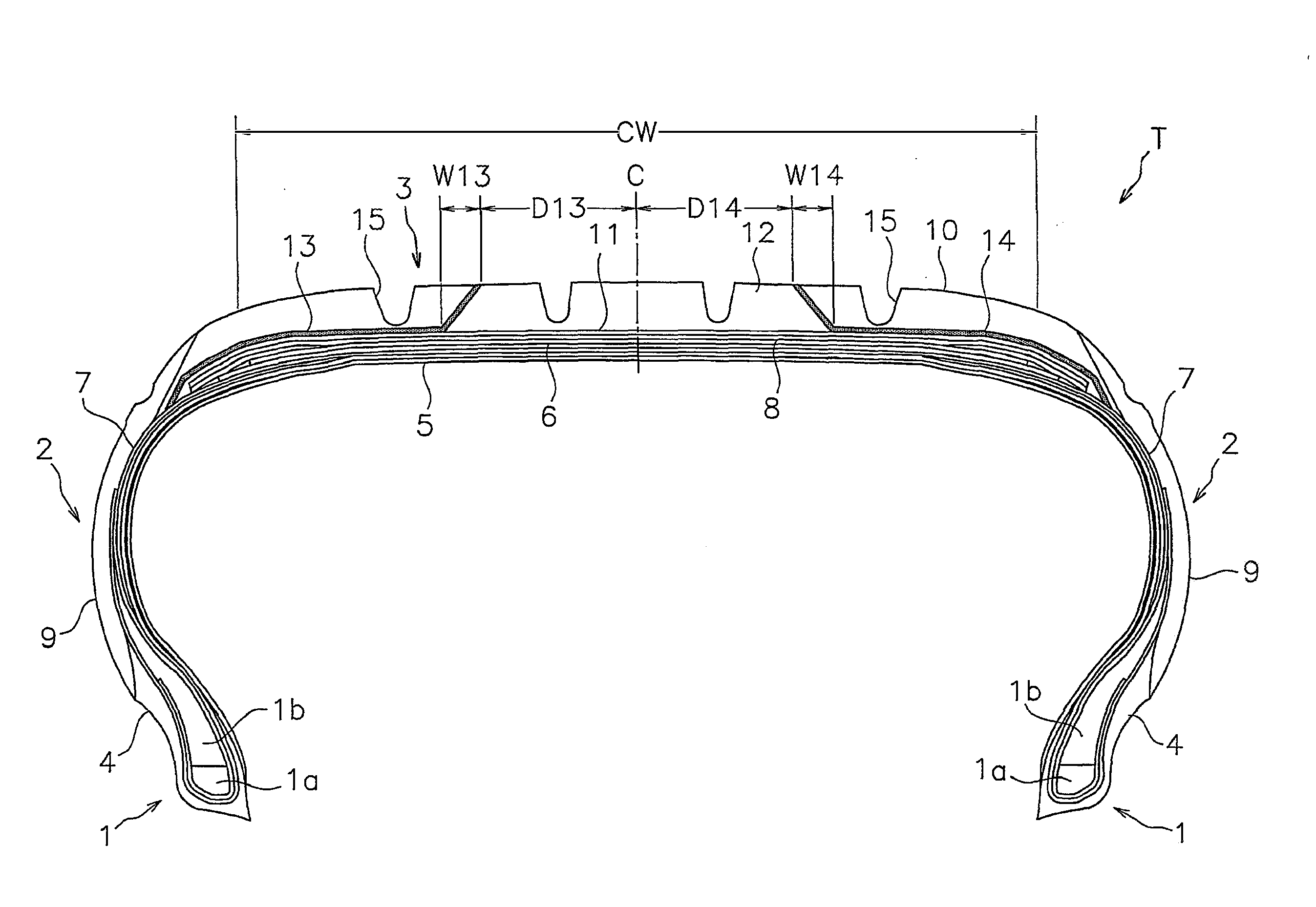
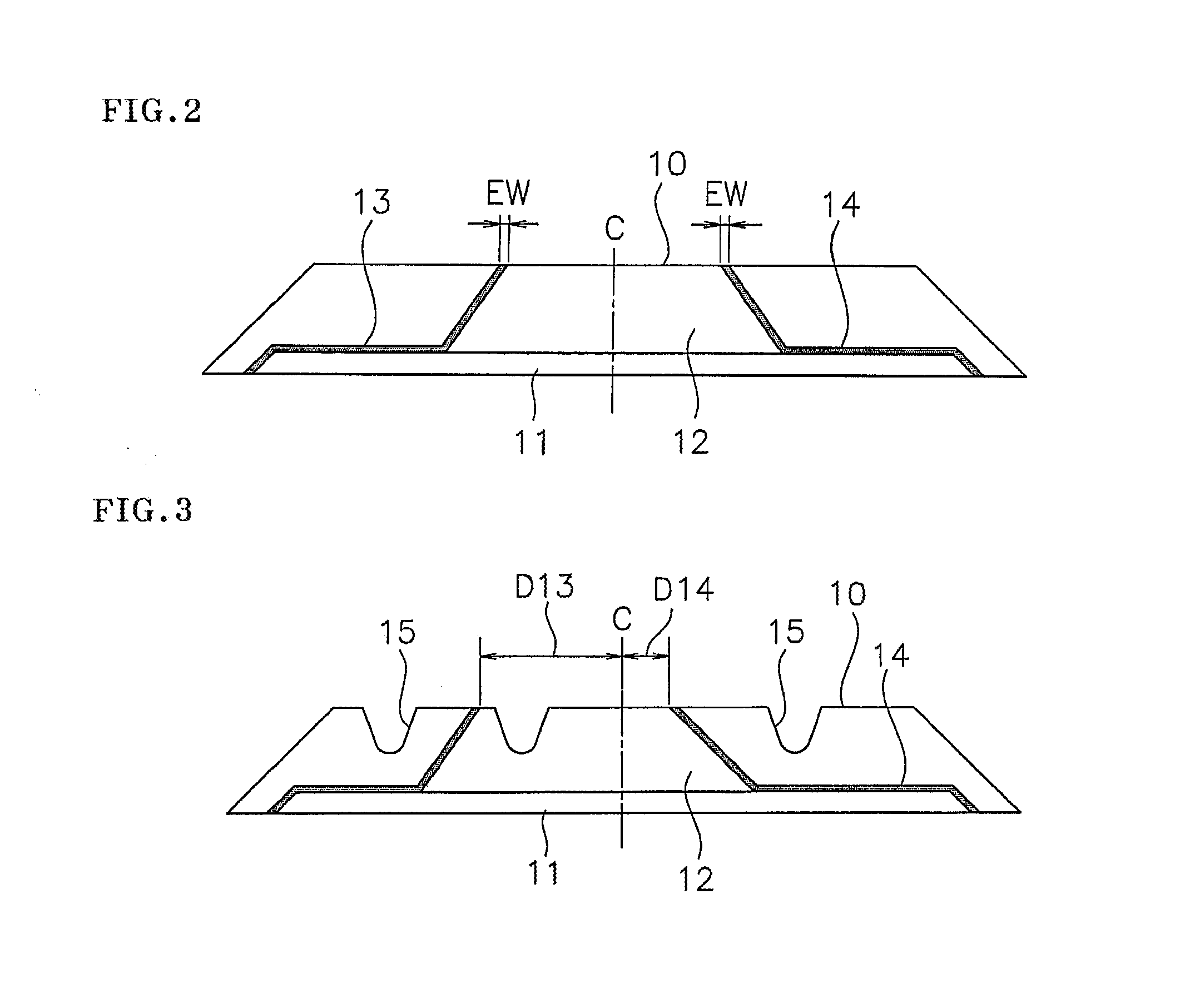
A pneumatic tire has a tread rubber made of a nonconductive rubber. The tread rubber is provided with a first and second conductive portions made of a conductive rubber. The first conductive portion extends radially inwardly from a ground-contacting surface, extends to one side in tire width direction, and reaches a carcass layer or a side wall rubber. An exposed position of the first conductive portion is separated from a tire equator at a distance is equal to or more than 10% of a ground-contacting width. The second conductive portion extends radially inwardly from the ground-contacting surface, extends to another side in tire width direction, and reaches the carcass layer or the side wall rubber. An exposed position of the second conductive portion is separated from the tire equator at a distance is equal to or more than 10% of the ground-contacting width.

Description

CROSS-REFERENCE TO RELATED APPLICATIONS[0001]This application is a divisional of application Ser. No. 13 / 397,854, filed on Feb. 16, 2012, which is based upon and claims the benefit of priority of the prior Japanese Patent Application No. 2011-206346, filed on Sep. 21, 2011 and Japanese Patent Application No. 2012-006361, filed on Jan. 16, 2012, the entire contents of which are incorporated herein by reference.BACKGROUND OF THE INVENTION[0002]1. Field of the Invention[0003]The present invention relates to a pneumatic tire which can discharge a static electricity generated in a vehicle body and a tire, to a road surface, and a manufacturing method of the pneumatic tire.[0004]2. Description of the Related Art[0005]Recently, there have been proposed a pneumatic tire including a tread rubber blended with silica at a high ratio in order to reduce the rolling resistance that largely affects the fuel consumption of a vehicle and / or to increase braking performance (WET braking performance) o...

Claims


Application Information

Patent Timeline
Patent Type & Authority Applications(United States)
IPC IPC(8): B60C19/08B60C13/00B29D30/52B60C11/00B60C11/03B60C15/00B60C9/02
CPCB60C19/082B60C15/00B60C13/00B60C9/02B60C11/005B29D2030/526B60C19/084B60C19/088B60C19/086B29D30/52B60C2011/0341B60C11/0304B29D30/60B60C19/08
Inventor SHINKAI, AKIHIKO
Owner TOYO TIRE & RUBBER CO LTD
Learn More