Supercharge Your Innovation With Domain-Expert AI Agents!

Integrated cross bar with mounting tab for grille

a cross bar and grille technology, applied in the field of integrated cross bars, can solve the problems of time-consuming, and achieve the effect of reducing errors and avoiding welding processes

Active Publication Date: 2016-10-13
INV HLDG INC
View PDF8 Cites 4 Cited by
  • Summary
  • Abstract
  • Description
  • Claims
  • Application Information

AI Technical Summary

Benefits of technology

The present invention aims to solve the problems of mounting tabs by eliminating the need for separate mounting tabs and cross bars, reducing welding processes, and decreasing errors and re-works. Additionally, it aims to eliminate the need for manual measuring, locating, and positioning of mounting tabs, as well as the need for manual setting of critical depth.

Problems solved by technology

All of these are time consuming and detract from the appearance of the grille.

Method used


Image

  • Integrated cross bar with mounting tab for grille
  • Integrated cross bar with mounting tab for grille
  • Integrated cross bar with mounting tab for grille

Examples


Embodiment Construction

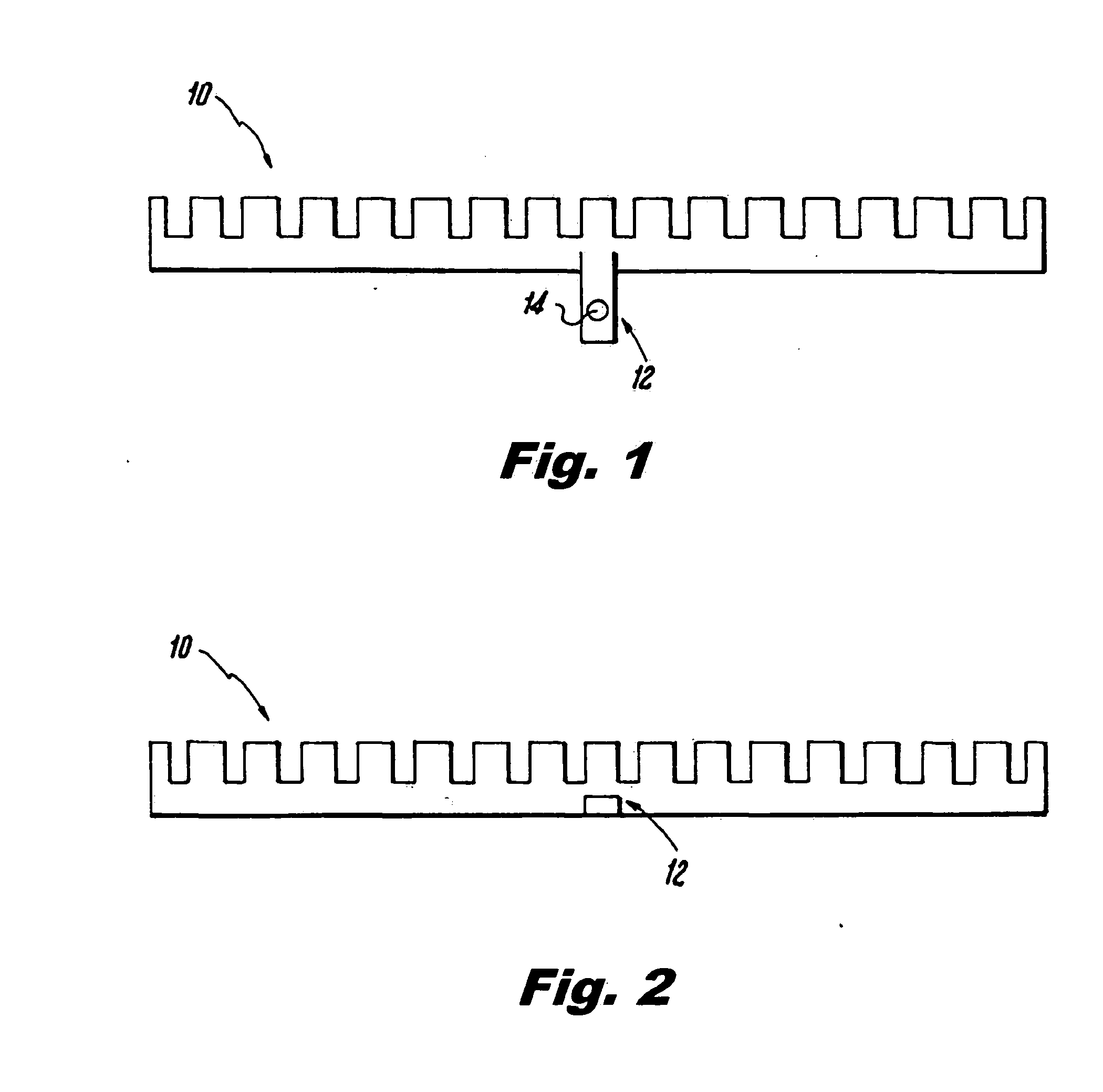
[0038]FIG. 1 shows the cross bar 10 having a mounting tab 12 with a through hole 14, prior to the mounting tab 12 being bent into position.

[0039]FIG. 2 shows the cross bar 10 having the mounting tab 12, after the mounting tab is bent into position.

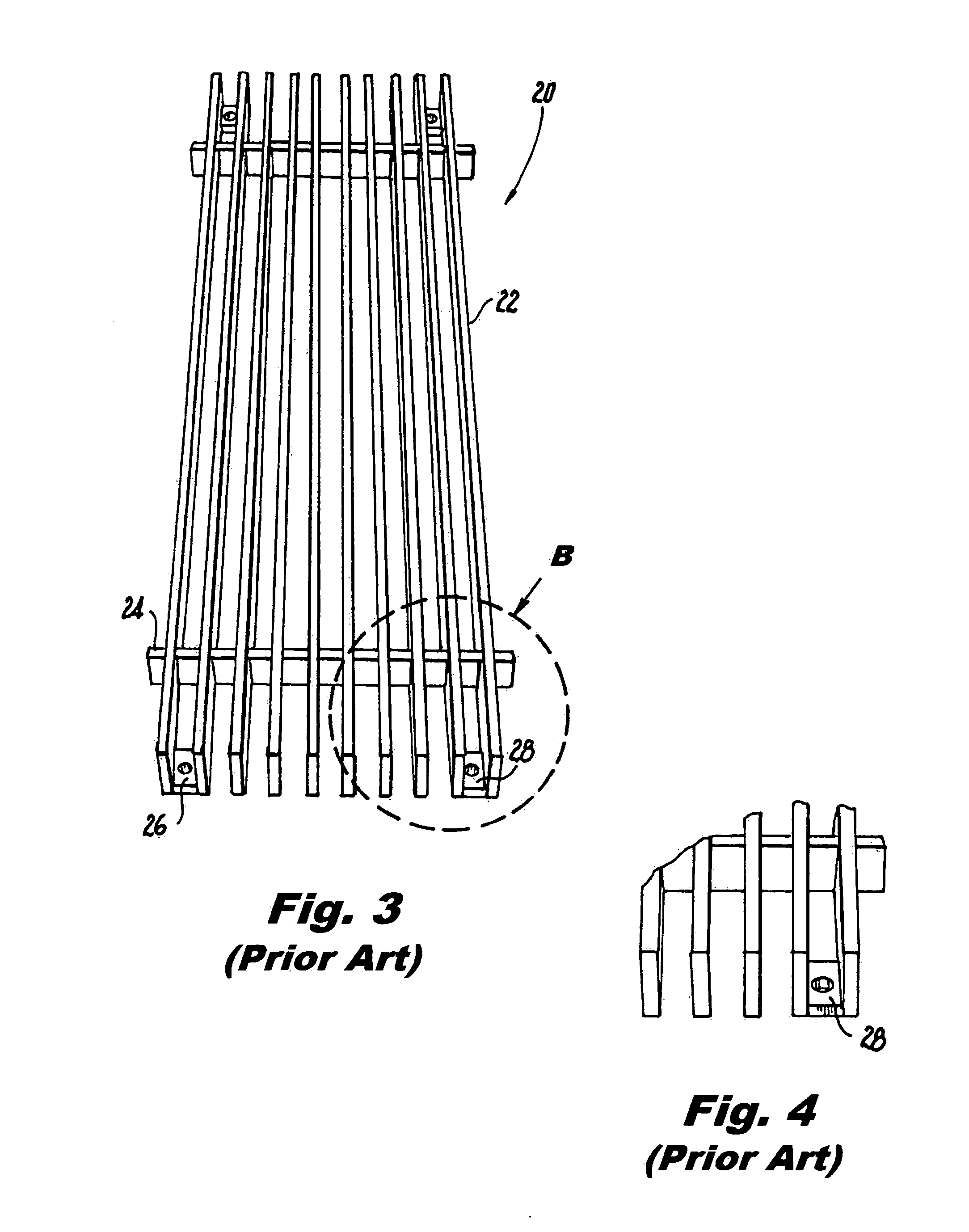
[0040]FIG. 3 shows a prior art linear bar grille 20 having linear bars 22, a cross bar 24, and mounting tabs 26 and 28. The mounting tabs 26 and 28 are welded between open spaces between linear bars 22.

[0041]FIG. 4 shows a sectional view through section B of FIG. 3.

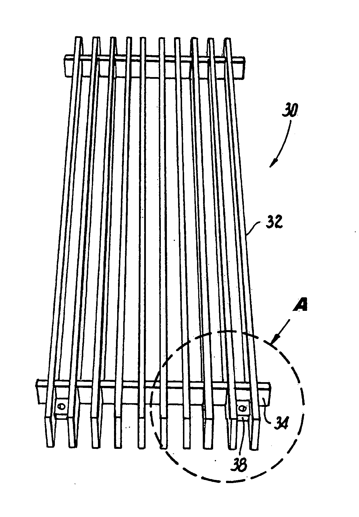
[0042]FIG. 5 shows the linear bar grille 30 of the present invention having linear bars 32, a cross bar 34, and mounting tabs 36 and 38 that are part of the cross bar 34.

[0043]FIG. 6 shows a sectional view through section A of FIG. 5.

[0044]FIG. 7 shows a top view of a prior art linear bar grille 40 having a cross bar 42 and a prior art welded tab 44.

[0045]FIG. 8 is a sectional view through section A of FIG. 7 showing the prior art welded tab 44.

[0046]FIG. 9 shows a bottom view o...


PUM


Abstract

A cross bar and mounting tab being a single piece for mounting a linear bar grille.

Description

FIELD OF THE INVENTION[0001]The present invention relates to an integrated cross bar having a mounting tab or tabs for a linear bar grille.BACKGROUND OF THE INVENTION[0002]U.S. Pat. No. 5,082,083 relates to a wall mounted stereo speaker assembly wherein the woofer of the speaker is mounted in the assembly wall frame and the tweeter is both mounted in and self-contained within the assembly wall frame. Installation requires a circular opening be cut in the wall to enable the rear portion of the woofer to extend through the dry wall or sheetrock and two holes drilled in the wall to accommodate the support bolts to retain the wall mounted speaker assembly on the wall.[0003]U.S. Pat. No. 5,623,791 relates to a protective grille assembly mountable over a window opening in a wall, that includes a grill panel having a plurality of parallel spaced vertical bars fixed to a plurality of parallel spaced horizontal bars. A plurality of fastening brackets mount the grille panel to the wall to cov...

Claims


Application Information

Patent Timeline
Patent Type & Authority Applications(United States)
IPC IPC(8): E04C2/40
CPCE04C2/40E06B9/01F24F13/084
Inventor BRUHNKE, LYNNEROEPER, DANIEL
Owner INV HLDG INC
Features
  • R&D
  • Intellectual Property
  • Life Sciences
  • Materials
  • Tech Scout
  • Unparalleled Data Quality
  • Higher Quality Content
  • 60% Fewer Hallucinations
Learn More