Transducer Mounted Between Two Spaced-Apart Interior Surfaces Of A Cavity In The Wall Of A Flow Tube

a technology of flow tube and transducer, which is applied in the field of acoustic transducers, can solve the problems of relatively high cost of wetted transducers, and achieve the effect of preserving wetted transducer performance and reducing costs

Inactive Publication Date: 2016-10-20
ONICON INC
View PDF1 Cites 2 Cited by
  • Summary
  • Abstract
  • Description
  • Claims
  • Application Information

AI Technical Summary

Benefits of technology

[0006]One aspect of the invention is that a non-penetrating slot, orthogonal to the flow passage, may be made into the flow tube to provide a mounting surface and an acoustic window for a piezoelectric element. The element is bonded to the slot surface adjacent to the flow passage after which the remainder of the slot is encapsulated. The shape of the slot enables the flow tube to continue to maintain fluid pressure even though the window between the element and fluid can be thin. Thus, wetted transducer performance is preserved while costs are reduced.
[0007]Another aspect of the invention is that it provides broad-area continuous electrical connection across the contact surfaces of the elements. This enables elements to continue to perform even though they may be mechanically fractured.

Problems solved by technology

However, the wetted transducer cost is relatively high because it is configured as a separate part that fits into a dedicated mounting assembly on the flow tube.

Method used


Image

  • Transducer Mounted Between Two Spaced-Apart Interior Surfaces Of A Cavity In The Wall Of A Flow Tube
  • Transducer Mounted Between Two Spaced-Apart Interior Surfaces Of A Cavity In The Wall Of A Flow Tube
  • Transducer Mounted Between Two Spaced-Apart Interior Surfaces Of A Cavity In The Wall Of A Flow Tube

Examples


Embodiment Construction

[0017]In studying this Detailed Description, the reader may be aided by noting definitions of certain words and phrases used throughout this patent document. Wherever those definitions are provided, those of ordinary skill in the art should understand that in many, if not most, instances such definitions apply both to preceding and following uses of such defined words and phrases.

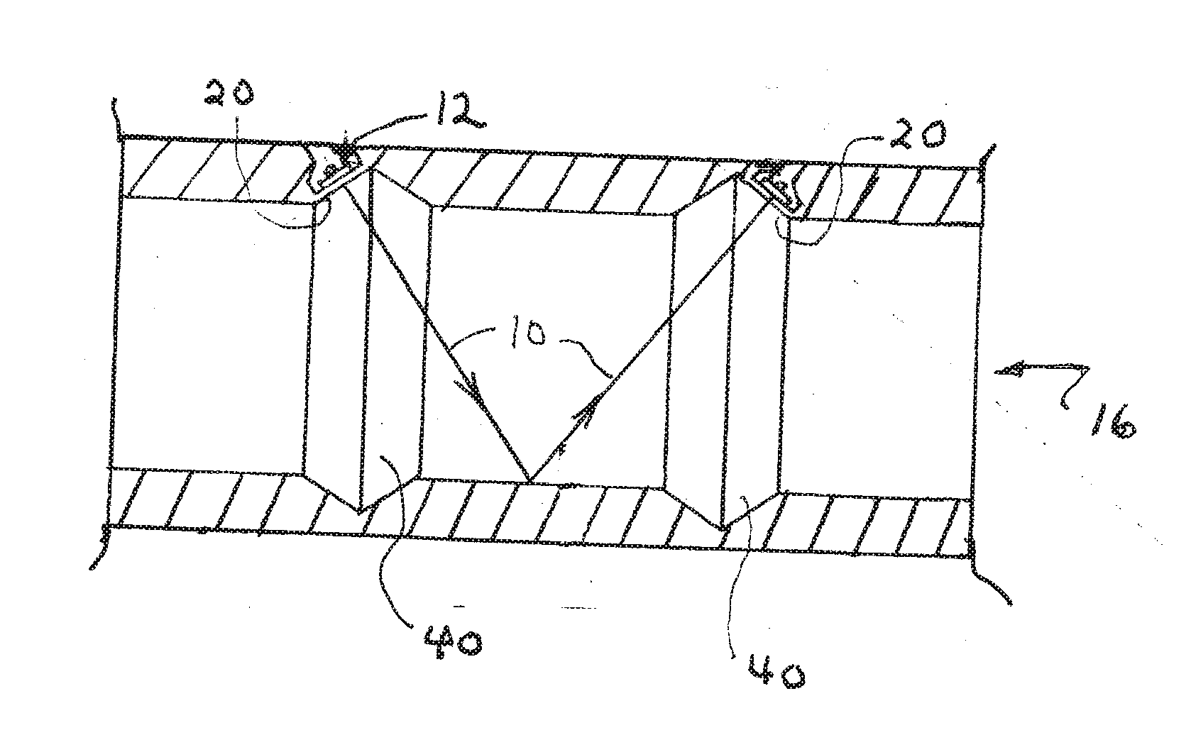
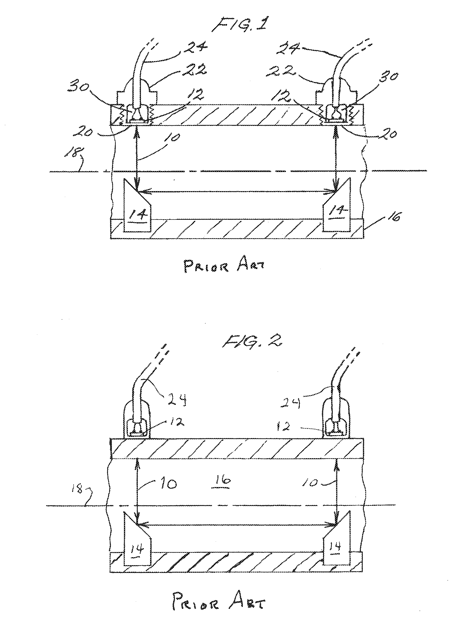
[0018]A prior art transit-time flow meter, depicted in FIG. 1, employs post reflectors 14 to define an acoustic path 10, indicated by arrowheaded lines extending between two transducers 12 that transmit and receive ultrasonic signals. These signals are electronically processed to yield a measurement of flow rate. The transducer elements 12 are mounted in a housing 22 with acoustic windows 20, that thread into openings on the flow tube 16 so that the windows are in direct contact with fluid flowing along the axis 18 of the flow tube 16. The elements are electrically isolated whereby both wires lead out, and ...


PUM


Abstract

An ultrasonic flow meter comprises a cavity disposed in the wall of a flow tube. This cavity is preferably elongated along a direction perpendicular to a flow axis and has a flat interior surface portion proximal an interior surface of a wall of the flow tube. A piezoelectric transducer has a surface bonded to the flat interior surface portion of the cavity so as to transmit and receive acoustic signals through a thin window in the wall of the flow tube. An encapsulant, which may be combined with other elements, such as a mechanical strengthening piece, bonds the second side of the piezoelectric wafer to a second surface of the cavity. In a particular preferred embodiment, the cavity may be a dovetailed groove cut into a wall of the flow tube.

Description

BACKGROUND INFORMATION[0001]This invention pertains to acoustic transducers, and particularly to mounting configurations for ceramic piezoelectric elements of the flat wafer type that are used in many industrial, commercial and medical applications such as flow meters.[0002]Prior art acoustic flow meters typically position transducer elements behind protective windows. Although transducers may be mounted on the outside of a flow tube containing the flowing fluid, the best measurement performance is obtained using wetted transducers because of their intimate acoustic coupling to the fluid and lack of acoustic beam corruption when the beam propagates through the flow tube wall. However, the wetted transducer cost is relatively high because it is configured as a separate part that fits into a dedicated mounting assembly on the flow tube.[0003]The inventor teaches a transducer bonded to a thin wetted window and encapsulated with rigid material to provide adequate strength for high press...

Claims


Application Information

Patent Timeline
Patent Type & Authority Applications(United States)
IPC IPC(8): G01F1/66
CPCG01F1/667G01F1/662
Inventor FELLER, MURRAY F.
Owner ONICON INC
Why Eureka
Try Eureka