Pneumatic tire with tread having wave shaped circumferential groove

a technology of circumferential grooves and pneumatic tires, which is applied in the field of pneumatic tires, can solve the problems of increasing tire noise and reducing the performance of wet braking when the tire is worn, and achieves the effect of not reducing tire noise and wet performan

Inactive Publication Date: 2014-07-08
THE YOKOHAMA RUBBER CO LTD
View PDF21 Cites 2 Cited by
  • Summary
  • Abstract
  • Description
  • Claims
  • Application Information

AI Technical Summary

Benefits of technology

[0008]However, by only increasing and decreasing the groove widths as in the related art, wet braking performance when the tire is worn may decrease substantially in some cases. It is thus an object of the invention to provide a pneumatic tire in which both of wet performance and tire noise performance are not reduced and at least one of them is improved when the tire is worn.
[0015]In the pneumatic tire according to the above aspect, both of the wet performance and the tire noise performance are not reduced when the tire is worn and at least one of them can be improved.

Problems solved by technology

However, during traveling on a dry road, groove widths and groove areas of the straight grooves extending in the circumferential direction rapidly shrink and expand to initial states in the contact patch due to a tire deformation to cause vibration in side walls of the grooves.
This vibration makes air vibrate in the circumferential grooves with air cavity resonance, and increases tire noise.
However, by only increasing and decreasing the groove widths as in the related art, wet braking performance when the tire is worn may decrease substantially in some cases.

Method used


Image

  • Pneumatic tire with tread having wave shaped circumferential groove
  • Pneumatic tire with tread having wave shaped circumferential groove
  • Pneumatic tire with tread having wave shaped circumferential groove

Examples


examples

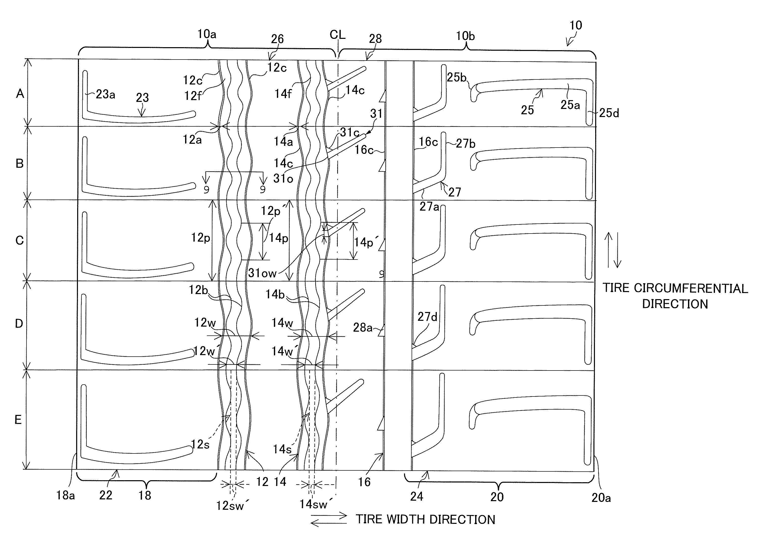
[0078]To study effects of this tread pattern 10 of the tire 1, tires were produced experimentally. Tire size was 196 / 65R15. Rim size was 15×6.0 J. The tires having tread patterns including circumferential grooves and lug grooves of dimensions illustrated in the following Tables 1 to 6 indicated in FIGS. 10A to 15D were produced. As a vehicle used for studying tire performance, a sedan type passenger car of a 2-liter engine displacement was used. Internal pressure was 210 (kPa) for the tires of front wheels and rear wheels.

[0079]In the Tables 1 to 6 indicated in FIGS. 10A to 15D, columns, “Groove center position from CL” is expressed as a distances between the tire center line CL and center positions of the respective circumferential grooves. For the groove positioned on the inner side of the vehicle when the tire is mounted, the distance is added as a negative sign, while for the groove positioned on the outer side of the vehicle, the distance is added as a positive sign. For the gr...


PUM


Abstract

A pneumatic tire includes a plurality of circumferential grooves and a first land portion. The circumferential grooves extend continuously in a tire circumferential direction. The first land portion extends in the tire circumferential direction between a pattern end and one of the circumferential grooves in a shoulder region located outside the circumferential grooves in a tire width direction. The first land portion has first lug grooves extending from the pattern end in the tire width direction and closed without communicating with the circumferential grooves are arranged in the tire circumferential direction. At least one circumferential groove is wave-shaped with a constant groove width in the tire width direction at a tread surface and formed in a wave shape in the circumferential direction at the tread surface and groove bottom. The wave-shaped circumferential groove has a shorter cycle length of waves at the groove bottom than at the tread surface.

Description

CROSS-REFERENCE TO RELATED APPLICATIONS[0001]This application claims priority to Japanese Design Application No. JP2010-028578, filed on Nov. 30, 2010 and Japanese Patent Application No. JP2010-269252, filed on Dec. 2, 2010. The entire disclosures of Japanese Design Application No. JP2010-028578 and Japanese Patent Application No. JP2010-269252 are hereby incorporated herein by reference.BACKGROUND[0002]1. Field of the Invention[0003]The present invention relates to a pneumatic tire. More particularly, the present invention relates to a pneumatic tire whose wet performance and tire noise performance are not reduced or improve when the tire becomes worn.[0004]2. Background Information[0005]Conventionally, there is a known pneumatic tire having a tread pattern including a plurality of straight grooves extending in a tire circumferential direction in order to improve wet performance such as hydroplaning performance during traveling on a wet road. Such a tire can effectively drain out w...

Claims


Application Information

Patent Timeline
Patent Type & Authority Patents(United States)
IPC IPC(8): B60C11/04B60C11/03B60C11/13B60C13/00
CPCB60C11/1392B60C11/0304B60C11/0309B60C11/042B60C11/13B60C11/1315B60C13/001B60C2011/0346B60C2011/0381B60C2011/0383B60C2011/133Y10S152/90
Inventor EBIKO, MASAHIROENDO, KENICHIROMORITO, TAKUMITOKIZAKI, HIROSHIKOJIMA, HIROYUKISAITOU, KENSUKE
Owner THE YOKOHAMA RUBBER CO LTD
Why Eureka
Try Eureka