Lens driving device

Active Publication Date: 2016-10-27
TDK TAIWAN
View PDF3 Cites 7 Cited by
  • Summary
  • Abstract
  • Description
  • Claims
  • Application Information

AI Technical Summary

Benefits of technology

[0050]By taking such constitution, the particles tend to be easily trapped in the space formed between the outer peripheral side plane of the cylinder shape proj

Problems solved by technology

Therefore, if the inner diameter of the opening part which is formed at the base part is too large, the distance between the outer sides of the base part and the opening part is shortened, thereby the space to place the driving part on the base part will be lost.
When the lens collides against the periphery o

Method used


Image

  • Lens driving device
  • Lens driving device
  • Lens driving device

Examples


Example

First Embodiment

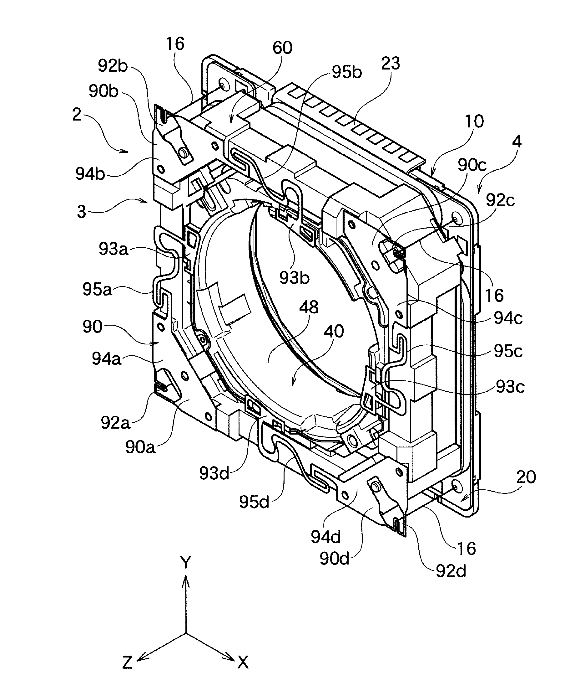
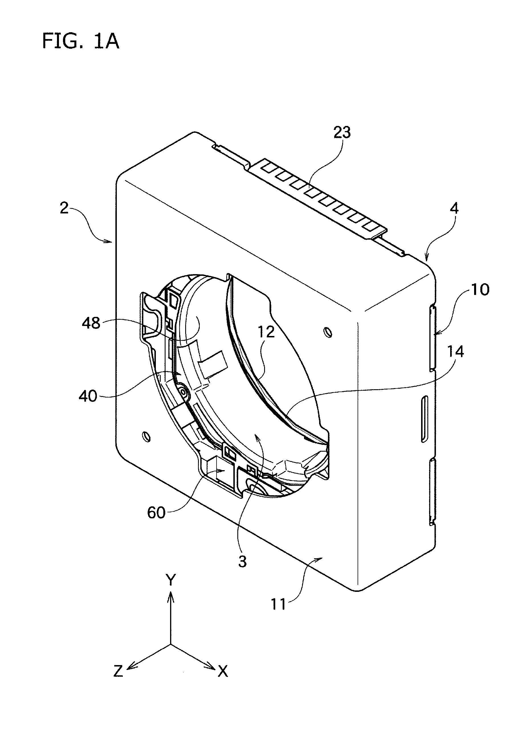
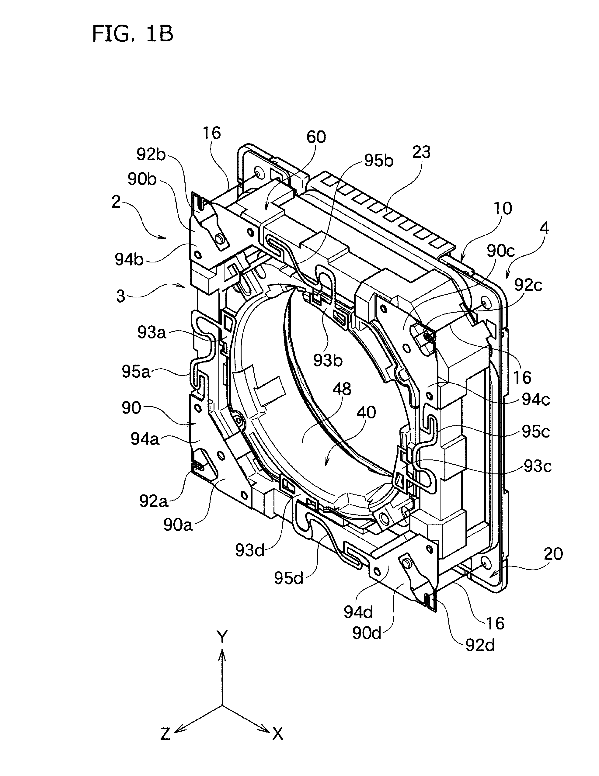
[0070]As shown in FIG. 1A, the lens driving device 2 according to one embodiment of the present invention comprises the fixing part 4, and the movable part 3 capable of moving against the fixing part 4. The fixing part 4 comprises the case 11 which covers the movable part 3 from the front side (from Z axis positive direction side), and the base part 10 covering the movable part 3 from the rear side (from Z axis negative direction side). The movable part 3 is placed at the inside of the case 11, and comprises the lens holder 40 holding the lens, and the flame 60 holding the lens holder 40 in a movable manner in the optical axis direction. At the inner peripheral plane 48 of the lens holder 40, the lens is installed however this is not shown in FIG. 1A.

[0071]The lens driving device 2 is used together with, for example, with the image sensor which is not shown in the figures. The image sensor is placed at the rear side (Z axis negative direction side) of the lens holder...

Example

Second Embodiment

[0123]The lens driving device 2 according to the second embodiment of the present invention comprises the same constitution and exhibits the same effect as the lens driving device 2 of the first embodiment, except for shown in below. Hereinafter, the parts which differ from the first embodiment will be mainly discussed, although some parts may overlap.

[0124]In the present embodiment, the opening part 12 shown in FIG. 6B may be a general opening part, and the oblique inner diameter Dxy1 and Dxy2 does not necessarily have to be larger than the first inner diameter Dx along X axis direction of the opening part 12, and also these do not necessarily have to be larger than the first inner diameter Dy along Y axis direction of the opening part 12. Also, in the present embodiment, a part of the lens 100 shown in FIG. 7 does not necessarily have to be in the opening part 12.

[0125]In the present embodiment, as shown in FIG. 6B, at the base part 10, the cylinder shape projecti...


PUM


Abstract

The present invention is a lens driving device comprising first driving coils 30a which relatively moves a lens holder 40 against a base part 10 along X axis perpendicular to an optical axis of a lens 100, and second driving coils 30b which relatively moves a lens holder 40 against a base part 10 along Y axis perpendicular to an optical axis. At the base part 10, an opening part 12 is formed where a part of the lens 100 is to be inserted in a movable manner along the driving plane. The oblique diameter Dxy1 and Dxy2 of the opening part 12 along the oblique direction positioned at the middle of X axis and Y axis, is larger than the first inner diameter Dx along X axis direction of the opening part 12, and also larger than the second inner diameter Dy along Y axis direction of the opening part 12. At the base part 10, the cylinder shape projection part 14 is formed along the periphery of the opening part 12.

Description

BACKGROUND OF THE INVENTION[0001]1. Field of the Invention[0002]The present invention relates to a lens driving device suitably used for instance as a camera module of a mobile phone or so.[0003]2. Description of the Related Art[0004]In the lens driving device suitably used for instance as the camera module of the mobile phone or so, the device has been developed which carries out the blur correction by moving the blur correction movable part including a lens holder holding the lens in the perpendicular direction along the optical axis (for example refer to following patent document 1). In order to carry out the blur correction by moving the blur correction movable part in the perpendicular direction along the optical axis, a part of a first driving part having a first driving axis, and a part of a second driving part having a second driving axis are provided to a base part.[0005]At the base part, an opening part is formed where at least part of the lens held by the lens holder is i...

Claims


Application Information

Patent Timeline
IPC IPC(8): G02B27/64G02B7/04
CPCG02B7/04G02B27/646G02B7/09G03B5/00G03B13/36H04N23/57H04N23/55H04N23/68G02B7/08G02B7/36G03B3/10G02B7/102
Inventor ICHIHASHI, SHUSUKE
Owner TDK TAIWAN
Why Eureka
Try Eureka