Image forming apparatus

a technology of image forming apparatus and density control patch, which is applied in the direction of electrographic process apparatus, instruments, optics, etc., can solve the problems of density sensor structure as described above that and the density sensor cannot accurately detect the density of the density control patch

Active Publication Date: 2016-10-27
CANON KK
View PDF9 Cites 10 Cited by
  • Summary
  • Abstract
  • Description
  • Claims
  • Application Information

AI Technical Summary

Problems solved by technology

Thus, if the surface of the pane of the exposure window of the density sensor is soiled by the toner scattered from the intermediary transferring component and the like, it becomes impossible for the density sensor to accurately detect the density of the density control patch.
That is, the soiling of the surface of the pane of the exposure window of the density sensor results in errors in the detection of the density of the density control patch.
However, even a density sensor structured as described above suffers from the following problem.
Therefore, with the elapse of time, the pane of the exposure window of the density sensor eventually becomes soiled with toner, and therefore, it sometimes occurs that the density of the density control patch is erroneously detected.
In the case of a structural arrangement in which a shutter such as the above-described one which has an opening and is movable in parallel to the lengthwise direction of the density sensor is provided with the referential reflective plate, if the opening of the shu

Method used


Image

  • Image forming apparatus
  • Image forming apparatus
  • Image forming apparatus

Examples


embodiment 1

1. Overall Structure and Operation of Image Forming Apparatus

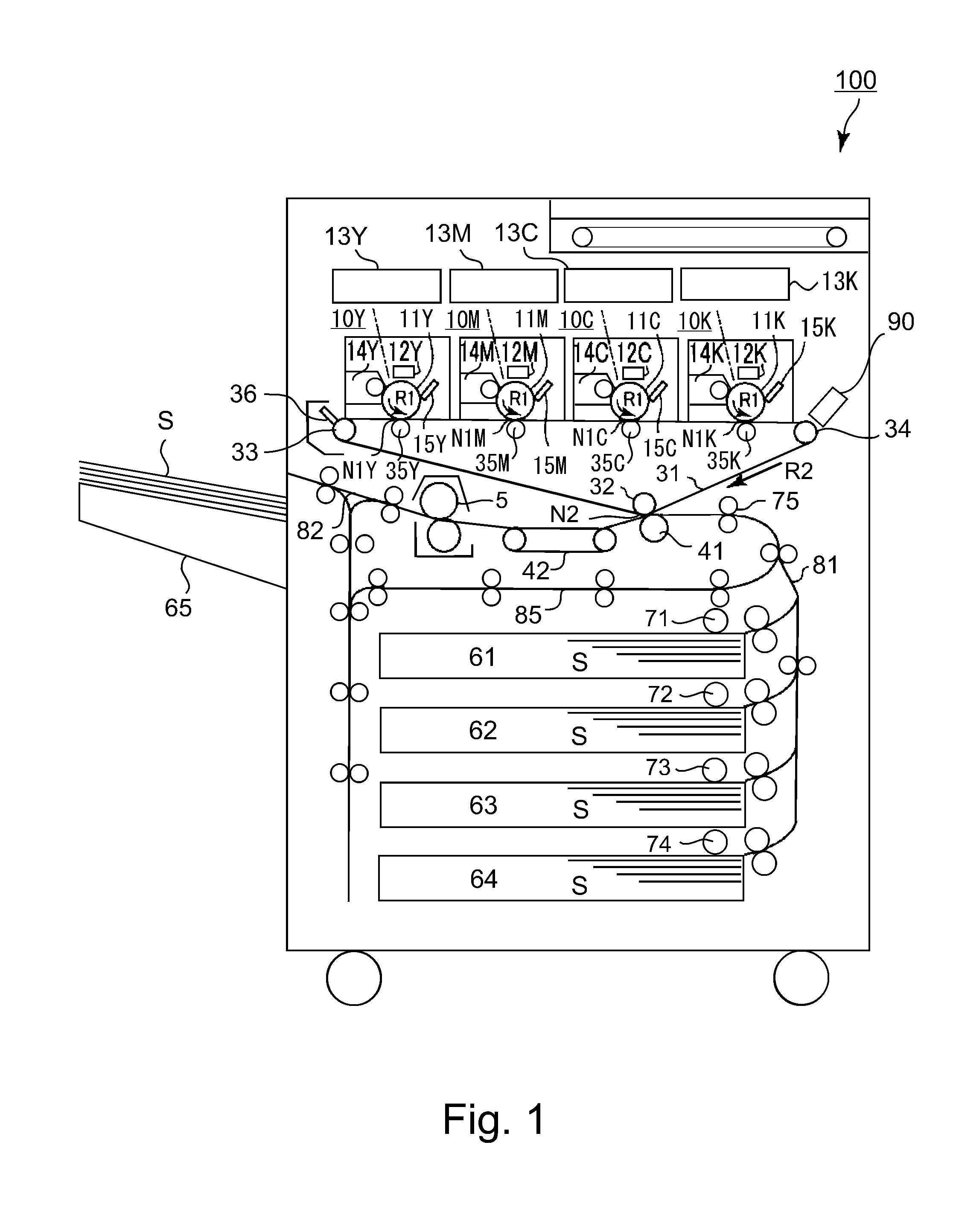
[0020]FIG. 1 is a schematic sectional view of the image forming apparatus 100 in the first of preferred embodiments of the present invention. This image forming apparatus 100 is a color image forming apparatus of the so-called intermediary transfer type, and also, of the so-called tandem type. That is, the image forming apparatus 100 has multiple image forming sections, more specifically, the first, second, third and fourth image forming sections 10Y, 10M, 10C and 10K. These image forming sections 10Y, 10M, 10C and 10K are aligned along the horizontal section of the intermediary transfer belt 31 of the image forming apparatus 100. They form yellow (Y), magenta (M), cyan(C) and black (K) images, respectively. The image forming apparatus 100 is enabled to form a full-color image on a sheet S of recording medium such as recording paper with the use of an electrophotographic method, in response to image formation signals sent ...

embodiment 2

[0049]Next, another embodiment of the present invention is described. The image forming apparatus 100 in this embodiment are basically the same in structure and operation as that in the first embodiment. Therefore, the components of the image forming apparatus 100 in this embodiment, which are the same as, or correspondent to, the counterparts in the first embodiment, in function and structure, and are given the same referential codes as those given to the counterparts, and are not described here.

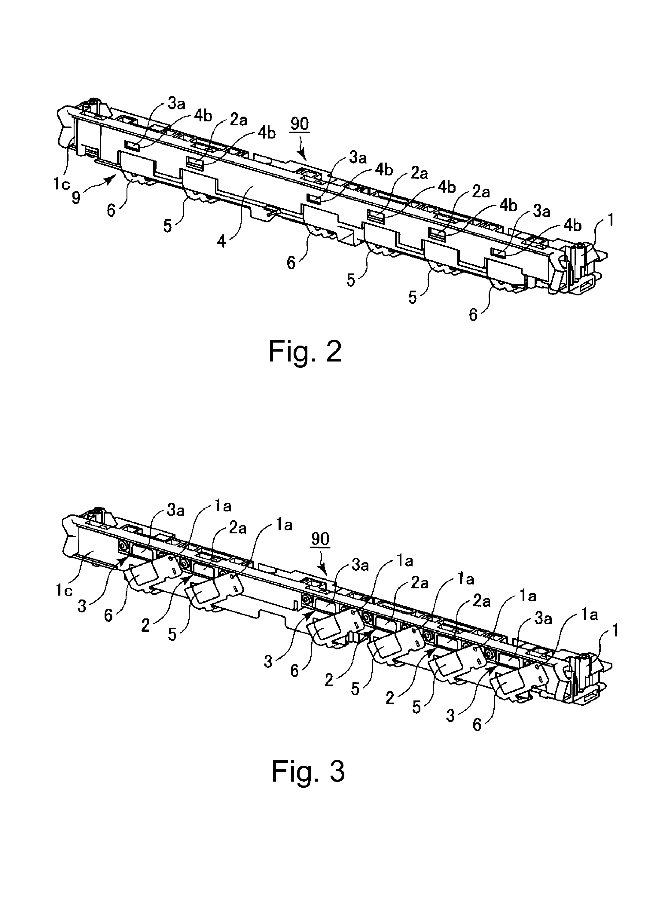
[0050]FIG. 7 is a plan view of the shutter mechanism 9 of the sensor unit 90 in this embodiment, as seen from the inward side (where density sensor 2 and color registration sensor 3 are present) of the sensor holder 1.

[0051]In this embodiment, the sensor holder 1 is provided with a pair of stoppers 1b, which correspond in position only to the density sensors 2. Therefore, it does not occur that the second shutters 6 provided for the color registration sensors 3 come into contact with the se...


PUM


Abstract

An image forming apparatus includes optical sensor units provided opposed to an image bearing member; light blockers provided between the image bearing member and the optical sensor units, respectively, the blockers being movable between locking and exposing positions, respectively; calibration members provided where the light is incident when the blockers are in the blocking positions, respectively, the calibration members calibrating data acquired by the optical sensor units; a movable link connected with the blockers; a switching portion for switching the blockers between the exposing and blocking positions; and a positioning portion for determining the blocking position, the positioning portion being disposed at a position where at least one of the blockers is contacted to the positioning portion when the blockers are switched from the exposing positions to the blocking positions.

Description

FIELD OF THE INVENTION AND RELATED ART[0001]The present invention relates to an image forming apparatus, such as a copying machine and a printer, which uses an electrophotographic, electrostatic, or the like recording method.[0002]Generally speaking, an image forming apparatus which uses an electrophotographic or electrostatic recording method forms a toner image on its image bearing component, which is in the form of a drum or a belt, with the use of an optional image formation process. This toner image is directly transferred (direct transfer type) onto recording medium which is conveyed by a recording medium bearing component, or is temporarily transferred (primary transfer) onto an intermediary transferring component, and then, is transferred (secondary transfer) onto recording medium. As for a recording medium bearing component or an intermediary transferring component, an endless belt is widely in use.[0003]Next, an image forming apparatus of the so-called intermediary transfe...

Claims


Application Information

Patent Timeline
IPC IPC(8): G03G15/00G03G15/01
CPCG03G15/50G03G15/5054G03G15/5041G03G2215/00042G03G2215/00059G03G2215/00616
Inventor YAMANA, KENTARO
Owner CANON KK
Why Eureka
Try Eureka