Rectifier, Alternator, and Power Converter

Active Publication Date: 2016-10-27
HITACHI POWER SEMICON DEVICE
View PDF7 Cites 13 Cited by
  • Summary
  • Abstract
  • Description
  • Claims
  • Application Information

AI Technical Summary

Benefits of technology

[0021]The present invention provides a rectifier of the autonomous type synchronous rectification MOSFET to prevent chattering and t

Problems solved by technology

The diode is inexpensive but has a forward voltage drop causing a large power loss.
However, the method using the Hall elemen

Method used


Image

  • Rectifier, Alternator, and Power Converter
  • Rectifier, Alternator, and Power Converter
  • Rectifier, Alternator, and Power Converter

Examples


Example

[0099]As shown in FIG. 20, the rectifier 132z of the second comparative example is configured to include a control IC 108z different from that of the first comparative example shown in FIG. 17. The control IC 108z of the second comparative example is different from the first comparative example shown in FIG. 17 in that the determination circuit 103 is provided with a hysteresis.

[0100]Note that the control IC 108z of the second comparative example has the same structure as that of the control IC 108y of the first comparative example. A CMOS buffer 161z of the second comparative example has the same structure as that of the CMOS buffer 161y of the first comparative example.

[0101]A resistor 165 is connected between the non-inverted input terminal IN+ and the power supply voltage terminal VCC of the determination circuit 103. The output terminal OUT of the determination circuit 103 is connected with a CMOS inverter 164 and fed back to the inverted input terminal IN− through a resistor 1...

Example

[0129]The rectifier 132 of the first embodiment allows the capacitor 107 to have a small capacitance by preventing the chattering, and further can afford to supply the power to the control IC 108, which achieves the rectifier 132 having a small area and low cost, and further can suppress an occurrence of a noise due to the vibration of the voltage and current.

[0130]The rectifier 132 may have a diode for absorbing a surge connected in parallel with the rectification MOSFET 101. Such a configuration may provide the rectifier 132 with a surge absorbing function.

[0131]The number of the stages of the CMOS buffers constituting the gate drive circuit 105 may be set to a plurality of stages, for example, 3 stages.

[0132]FIG. 3 is a diagram showing a rectifier for the autonomous type synchronous rectification MOSFET that is a modification example of the first embodiment. The modification example of the first embodiment shown in FIG. 3 shows a configuration in which the rectifier of the autono...

Example

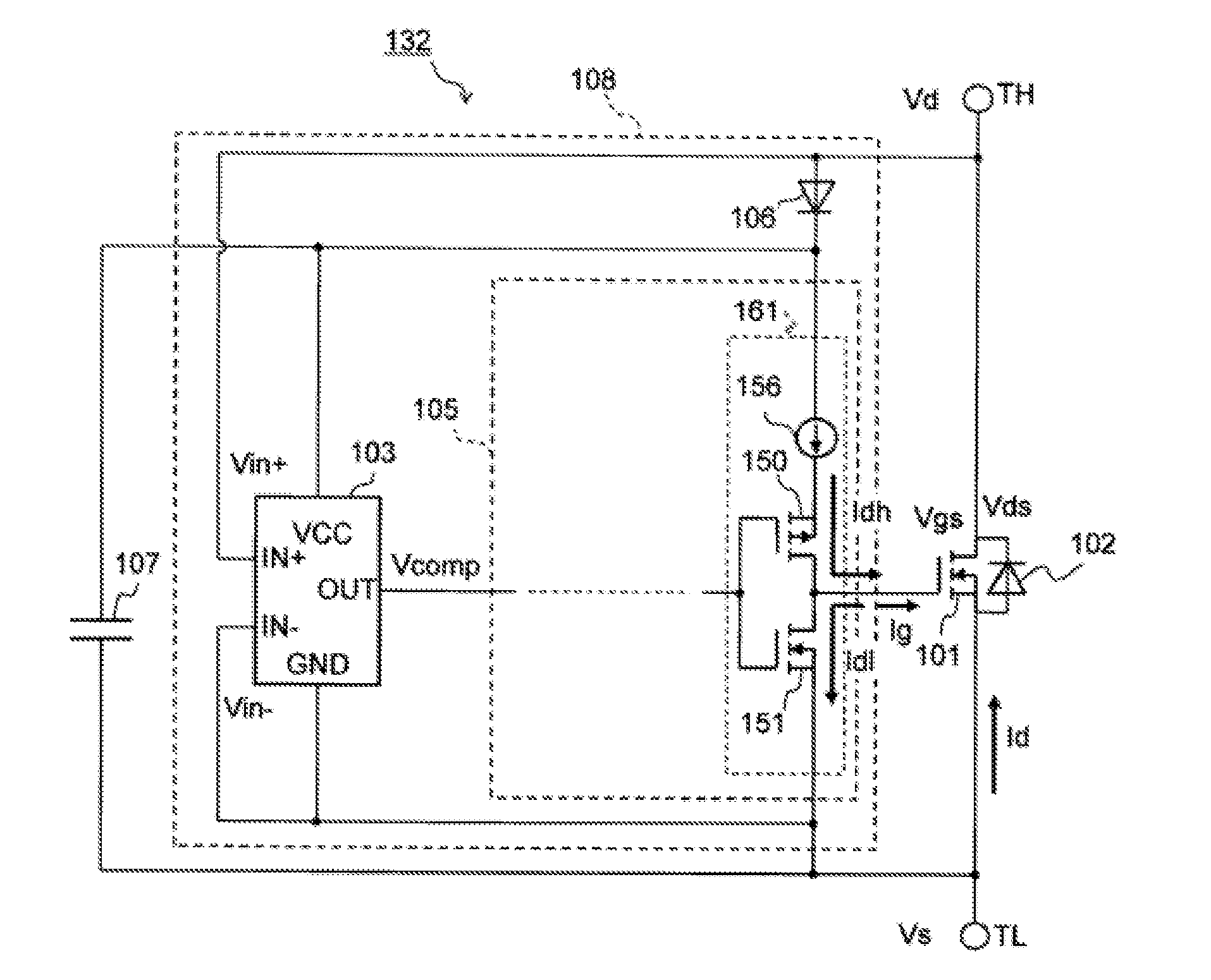
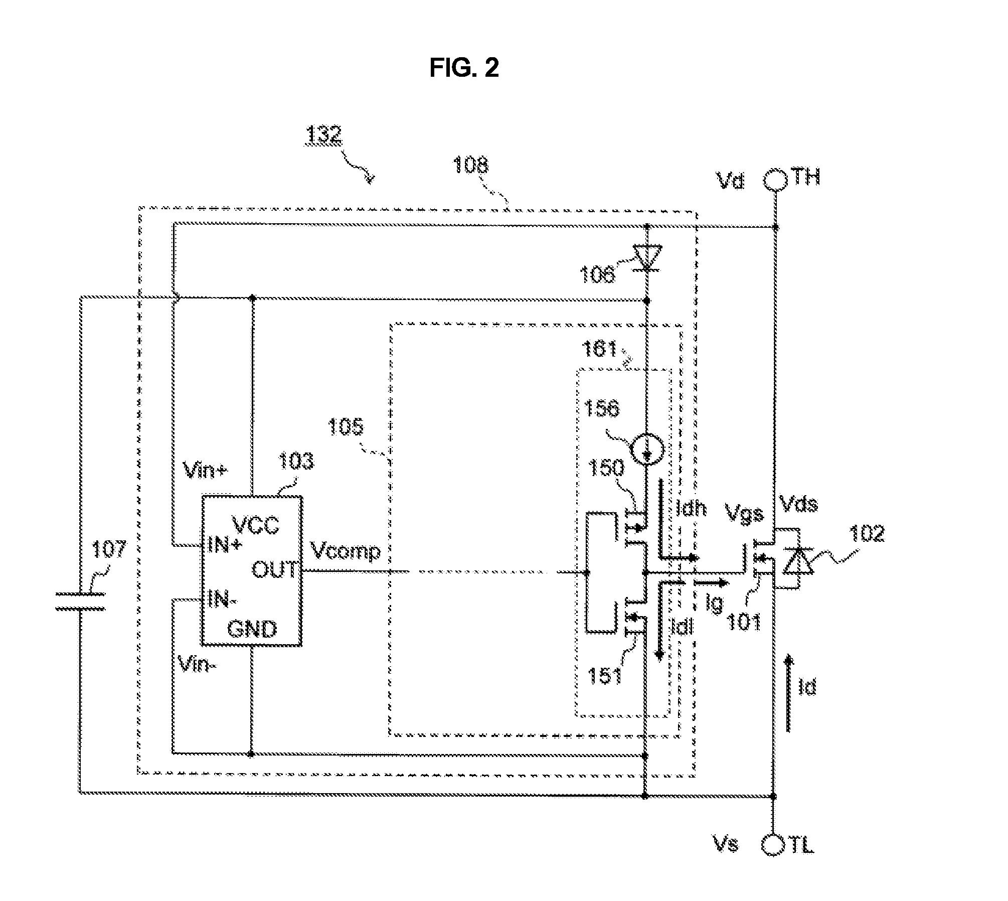
[0244]The rectifier 132a of the second embodiment shown in FIG. 10 has a control IC 108a different from the rectifier 132 of the first embodiment shown in FIG. 2. Further, the control IC 108a of the second embodiment has a gate drive circuit 105a different from that of the control IC 108 in the first embodiment.

[0245]The gate drive circuit 105a of the second embodiment has a CMOS buffer 161a of the final stage different from the gate drive circuit 105 of the first embodiment. The CMOS buffer 161a has a resistor R1 connected to the high-side P-type MOSFET 150 in series and on the path of the drain current Idh for turning on the gate of the rectification MOSFET 101. The resistor R1 may be connected with either the source or the drain of the high-side P-type MOSFET 150. The resistor R1 of the second embodiment is disposed in place of the constant-current circuit 156 of the first embodiment.

[0246]When turning on the rectification MOSFET 101, the gate current Ig flows from the high-side ...


PUM


Abstract

A rectifier including an autonomous type synchronous-rectification MOSFET is provided, which prevents chattering and through-current caused by a malfunction when a noise is applied. The rectifier includes: a rectification MOSFET for performing synchronous rectification; a determination circuit configured to input a voltage between a pair of main terminals of the rectification MOSFET, and to determine whether the rectification MOSFET is in on or off state on the basis of the inputted voltage; and a gate drive circuit configured such that a gate of the rectification MOSFET is turned on and off by a comparison signal from the determination circuit, and such that a time required to boost a gate voltage when the rectification MOSFET is turned on is longer than a time required to lower the gate voltage when the rectification MOSFET is turned off.

Description

TECHNICAL FIELD[0001]The present invention relates to a rectifier of autonomous type synchronous rectification MOSFET (Metal Oxide Semiconductor Field Effect Transistor), and an alternator and a power converter using this rectifier.BACKGROUND ART[0002]An alternator that generates electricity in an automobile has heretofore used a diode as a rectifier. The diode is inexpensive but has a forward voltage drop causing a large power loss. Contrastingly, in recent years, MOSFET has begun to be used as the rectifier for the alternator. Synchronous rectification of the MOSFET enables developing of a rectifier that has no forward voltage drop and raises a forward current at 0 Volt and generates a small power loss.[0003]A power supply outputs an AC power with a constant frequency, and therefore, when a MOSFET is used for a rectifier of the power supply, on-off control of the MOSFET can be performed by way of synchronization with a clock. However, the alternator outputs an AC power with a non-...

Claims


Application Information

Patent Timeline
IPC IPC(8): H02M7/04H02M1/08H03K17/16
CPCH02M7/04H02M1/08H03K17/163H02M7/219Y02B70/10H02M1/0029H02M7/2195H03K17/302H03K2017/307
Inventor ISHIMARU, TETSUYAONDA, KOHHEISAKANO, JUNICHIMORI, MUTSUHIRO
Owner HITACHI POWER SEMICON DEVICE
Why Eureka
Try Eureka