Mounting structure for console

US20050236859A1Inactive Publication Date: 2005-10-27TOYODA GOSEI CO LTD

Image

  • Mounting structure for console
  • Mounting structure for console
  • Mounting structure for console

Examples


Embodiment Construction

[0023] One embodiment of the present invention will now be described with reference to the drawings.

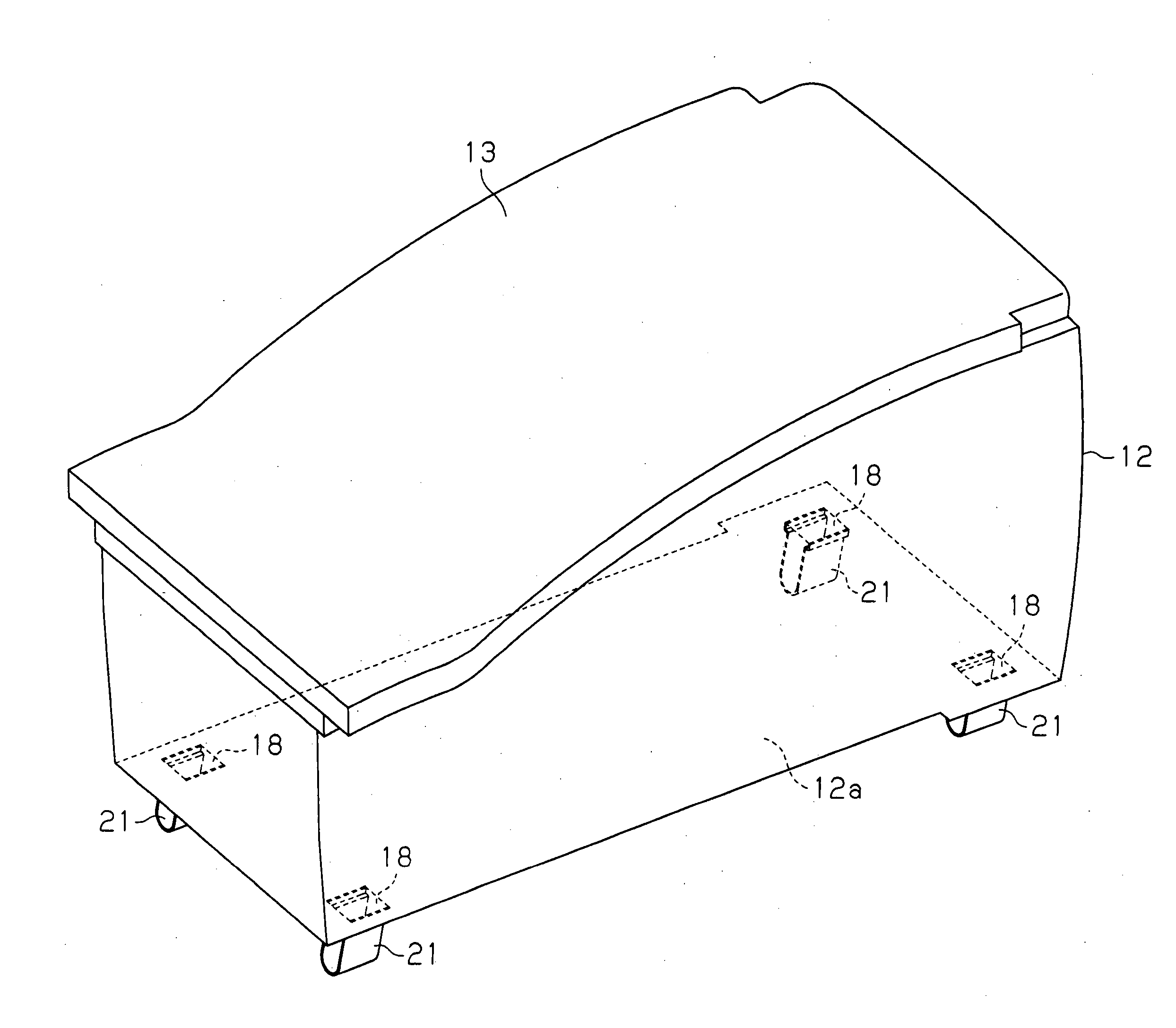
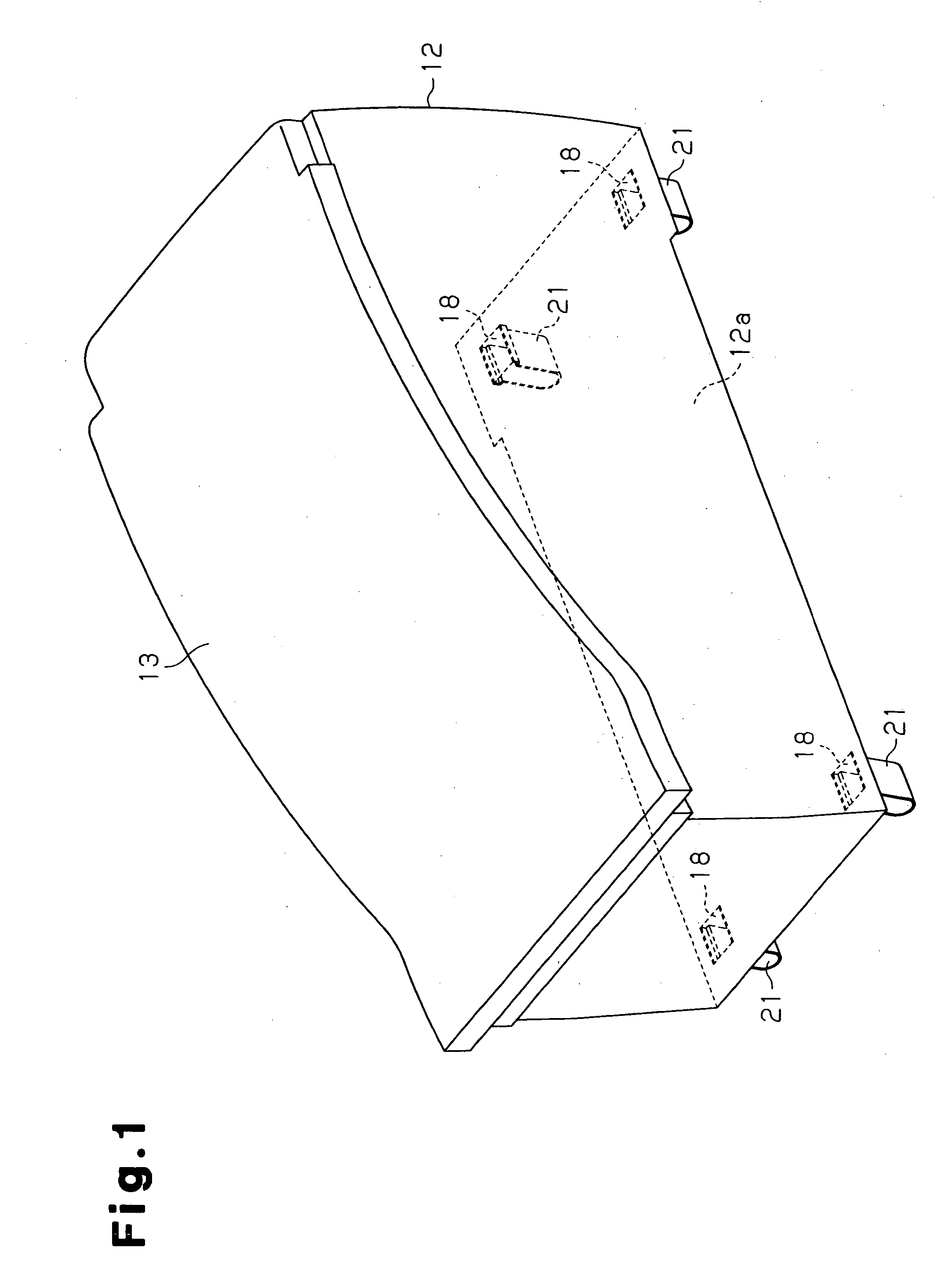
[0024] As shown in FIGS. 1 and 5, a console 11 includes a rectangular console body 12 having a bottom, a lid 13, a bottom cover 14 placed on a bottom wall 12a of the console body 12. The console 11 is located between the driver's seat and the front passenger seat in a passenger compartment of a vehicle. The longitudinal direction of the console 11 coincides with the front-to-rear direction of the vehicle. A pair of front and rear brackets 16 are fixed to a floor panel 15 forming the floor of the vehicle. The console 11 is attached to the brackets 16. The brackets 16 can be regarded as components that form part of the floor panel 15.

[0025] As shown in FIG. 3, the brackets 16 are located at a position corresponding to a front portion of the console body 12 (front position with respect to the front-to-rear direction of the vehicle) and a position corresponding to a rear portion of the ...


PUM


Abstract

A console is attached to brackets fixed to a floor panel of a vehicle. Each bracket has a pair of fitting holes. The console includes a console body having a rectangular bottom wall. An insertion hole is formed in each of the four corners of the bottom wall. Each insertion hole corresponds to one of the fitting holes. Clips are provided at portions of the bottom wall, each portion corresponding to one of the insertion holes. Each clip has two fitting portions that are arranged to face each other. When each clip is inserted into the corresponding fitting hole, the fitting portions are fitted to an inner wall of the fitting hole so that the console body is attached to the brackets. With the clips inserted into the fitting holes, a fastening member having two legs is inserted into each insertion hole so that the legs are located between the corresponding fitting portions to prevent the clip from being removed from the fitting hole.

Description

BACKGROUND OF THE INVENTION [0001] The present invention relates to a mounting structure for a console located between the driver's seat and the front passenger seat in a vehicle such as an automobile. [0002] Conventionally, a console is installed in a vehicle by using screws. However, installment with screws involves troublesome steps in which a worker has to get on and off a vehicle a number of times in an automobile assembly line. In this respect, for example, Japanese Laid-Open Patent Publication No. 8-11635 discloses a console that facilitates the assembly. The console of the publication includes a body. A rib projects downward from an inner surface of an upper wall of the body. A fixing clip is attached to the rib. On the other hand, a bracket is fixed to a floor tunnel to which the console is to be attached. The bracket has a slit. The fixing clip of the body is engaged with the slit so that the console is installed on the floor tunnel. This console does not require screws to...

Claims


Application Information

Patent Timeline
27 Oct 2005
Publication
US20050236859A1
IPC
B60N3/12; B60R7/04
CPC
B60R7/04
Inventors
SAKAKIBARA, YASUHIRO; IKUTA, HIROTO