Viscous strand damper assembly

Active Publication Date: 2009-05-07
ILLINOIS TOOL WORKS INC
View PDF14 Cites 12 Cited by
  • Summary
  • Abstract
  • Description
  • Claims
  • Application Information

AI Technical Summary

Benefits of technology

[0013]An advantage of the present invention is providing a damper that can be mounted remotely from the item to be controlled in an area otherwise unused, and which does not detract from usable space in the item or the environment around it.
[0014]Another advantage of the present invention is providing a damper that operates smoothly without startup variances.
[0015]Still another advantage of the present invention is providing a damper system that can be used wi

Problems solved by technology

However, there are ever increasing demands necessitating new and improved damper des

Method used


Image

  • Viscous strand damper assembly
  • Viscous strand damper assembly
  • Viscous strand damper assembly

Examples


Embodiment Construction

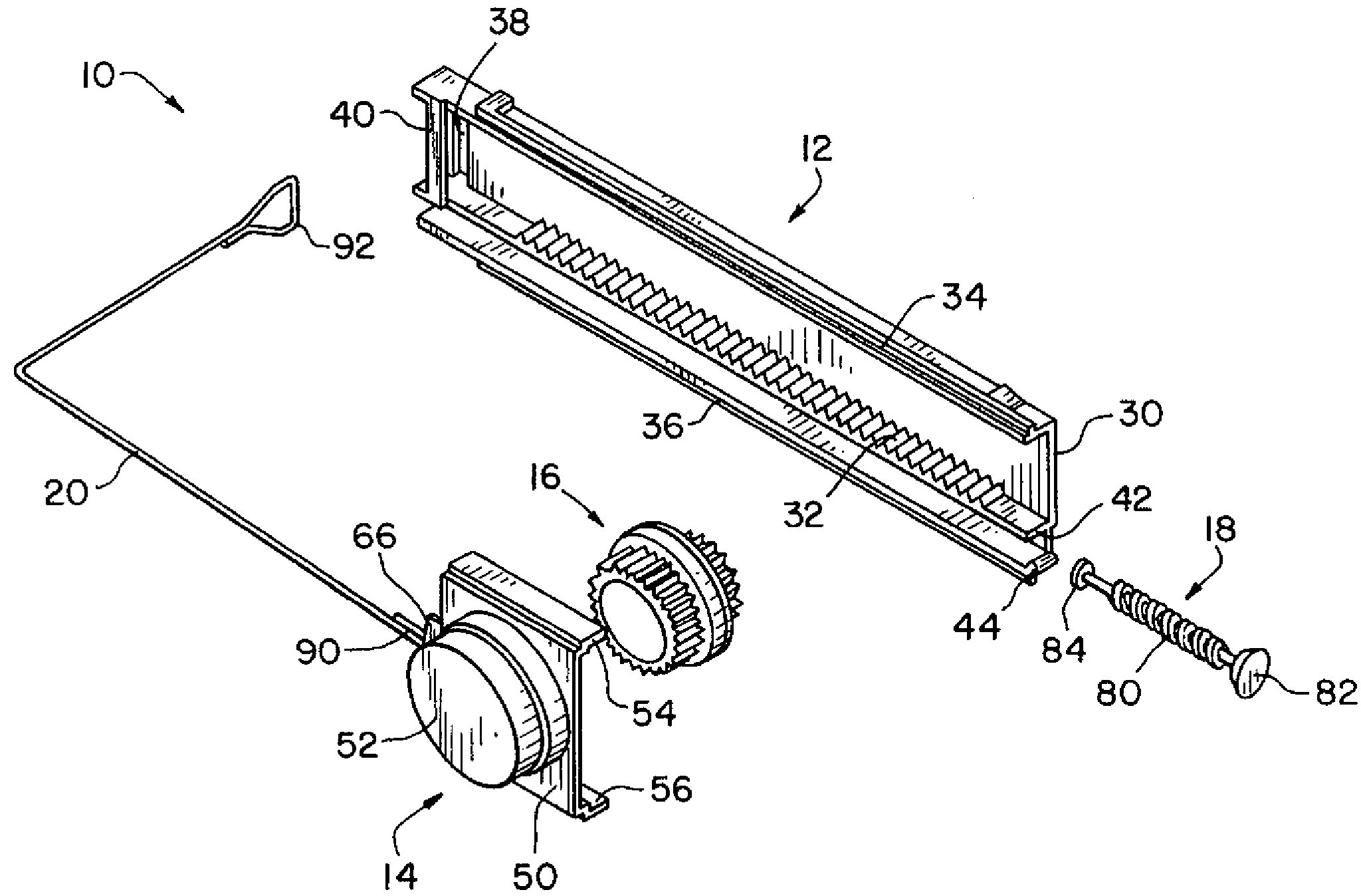
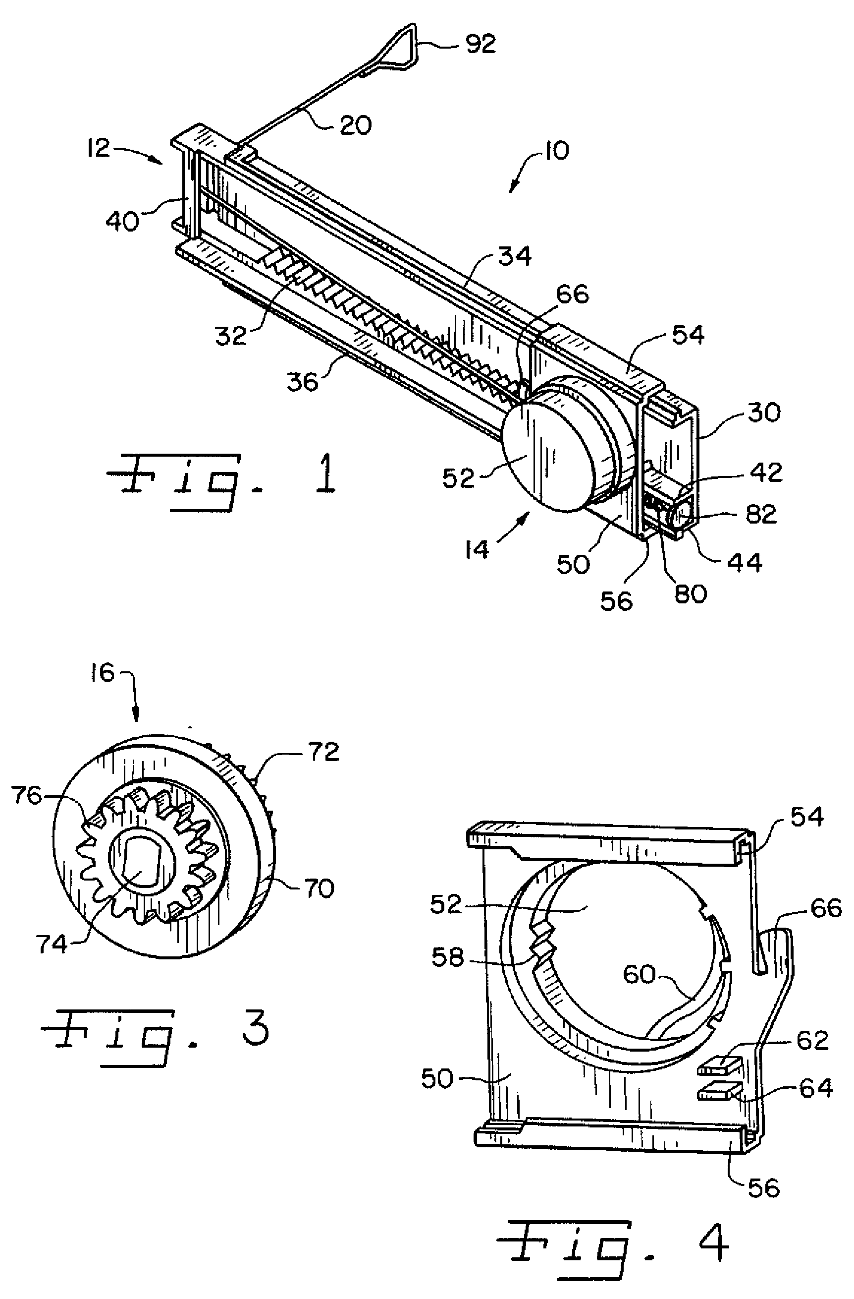
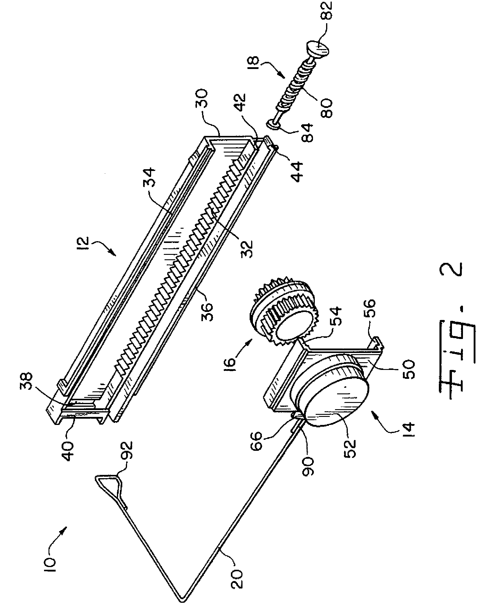
[0027]Referring now more specifically to the drawings and to FIGS. 1 and 2 in particular, numeral 10 designates a viscous strand damper assembly in accordance with the present invention. Damper assembly 10 includes a base 12 by which damper assembly 10 is positioned and mounted for use. A carriage 14 moves is engaged with base 12, and moves back and forth along base 12 via the interrelationship of a damper 16 carried within carriage 14 and operable along base 12. In the exemplary embodiment, a spring 18 is provided for moving carriage 14 in one direction; however, it should be understood that other return structures can be used. A tether 20 is connected to carriage 14 at one end thereof and to the item to be controlled at another end thereof.

[0028]Base 12 includes a base plate 30 for mounting assembly 10 in the vicinity of the article the movement of which is to be controlled. Accordingly, base plate 30 can be provided with suitable structures (not shown) such as holes for fasteners...


PUM


Abstract

A damper assembly includes a fixed rack gear, a rotary gear damper having a gear engaged with the rack gear, and a tether movable with the damper along the rack gear and connected to the movable object to be controlled by the damper. A biasing element normally urges the damper away from anti-rotation locking members.

Description

CROSS-REFERENCE TO RELATED APPLICATIONS[0001]This application is a Continuation-In-Part of co-pending U.S. patent application Ser. No. 11 / 546,100 filed on Oct. 11, 2006 which claims the benefit of U.S. Provisional Application Ser. No. 60 / 736,236 filed on Nov. 14, 2005. The contents of all such referenced patent applications are hereby incorporated by reference in their entirety as if fully set forth herein.FIELD OF THE INVENTION[0002]The present invention relates generally to dampers for controlling movement of things, and, more particularly, the invention pertains to viscous dampers that use a tether for attachment between the device to be controlled and the damper.BACKGROUND OF THE INVENTION[0003]It is known to use movement dampers in a wide variety of assemblies to control the movement of assembly components. In some situations, dampers are used to control movements of components that would otherwise move more suddenly and forcefully than desired. The damper may control movement ...

Claims


Application Information

Patent Timeline
IPC IPC(8): F16F9/00
CPCE05F5/00E05Y2201/21E05Y2201/254F16F9/12E05Y2600/46E05Y2900/538E05Y2201/266
Inventor ZEILENGA, CHAD K.BELLA, JOSEPH J.DOORNBOS, DAVIDCASCIO, JEFFERY
Owner ILLINOIS TOOL WORKS INC
Why Eureka
Try Eureka