Thread cutting device of sewing machine

Inactive Publication Date: 2008-10-16
JUKI CORP
View PDF5 Cites 9 Cited by
  • Summary
  • Abstract
  • Description
  • Claims
  • Application Information

AI Technical Summary

Benefits of technology

[0022]According to the fourth aspect of the invention, the second cam member is set to be the cylindrical cam having the drivers on the peripheral surface and one of the end faces in the axis direction and the second cam member has such a structure as to be disposed concentrically with the first cam member and to retain the first cam member on the inside. Furthermore, the first cam member is set to be the end cam having the drivers on both of the end faces. Consequently, it is possible to smoothly carry out the operations for catching and cutting the thread with a simple structure while reducing a space for the thread cutting device of the sewing machine.
[0023]According to the fourth aspect of the invention, moreover, it is possible to operate the first thread catching member and the second thread catching member in desirable timings and moving amounts with a simple structure by forming the respective drivers of the first cam member and the second cam member which are to be rotated axially in desirable phases and guiding amounts, for example. In addition, it is possible to set a relationship of an operation timing and a moving amount between the first thread catching member and the second thread catching member by setting the respective drivers formed on both of the end faces of the first cam member and the respective drivers formed on the peripheral surface and one of the end faces in the second cam member to have desirable phases and guiding amounts.
[0024]According to the fifth aspect of the invention, the respective followers of the first power transmitting member and the second power transmitting member are moved backward and held in a position in which they are not engaged with the driver of the first cam member through the abutting portion provided in the driver of the second cam member. Accordingly, the respective followers are held in the abutting portion during a sewing work. Consequently, it is possible to prevent an interference of the driver of the first cam member to be rotated together with the lower shaft and the respective followers of the first power transmitting member and the second power transmitting member. Thus, it is possible to implement a smooth sewing operation.
[0025]According to the sixth aspect of

Problems solved by technology

In general, it is hard to control the servomotor in a low speed region.
For this reason, it is difficult to set an operating speed of the thread catching body 610 interlocked with the lower shaft to be sufficiently low.
There is a problem in that sewing quality is deteriorated in a next sewing work due to the excessive pull-out.
On the other hand, in the case in which the needle thread and the bobbin thread T which remain

Method used


Image

  • Thread cutting device of sewing machine
  • Thread cutting device of sewing machine
  • Thread cutting device of sewing machine

Examples


Example

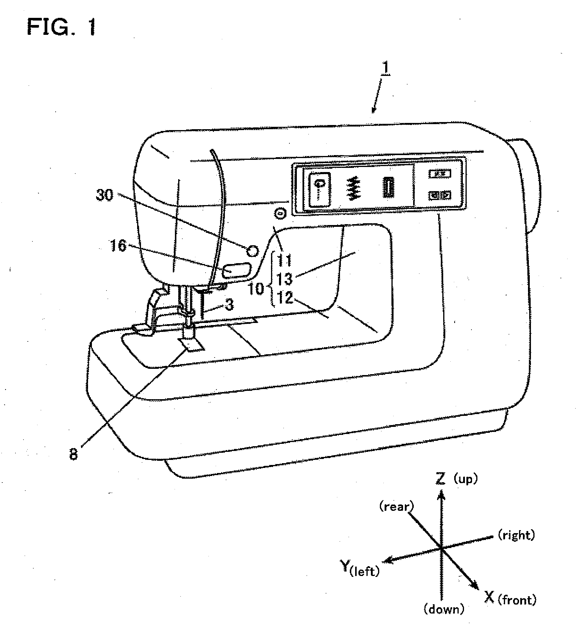
(Whole Structure of Sewing Machine)

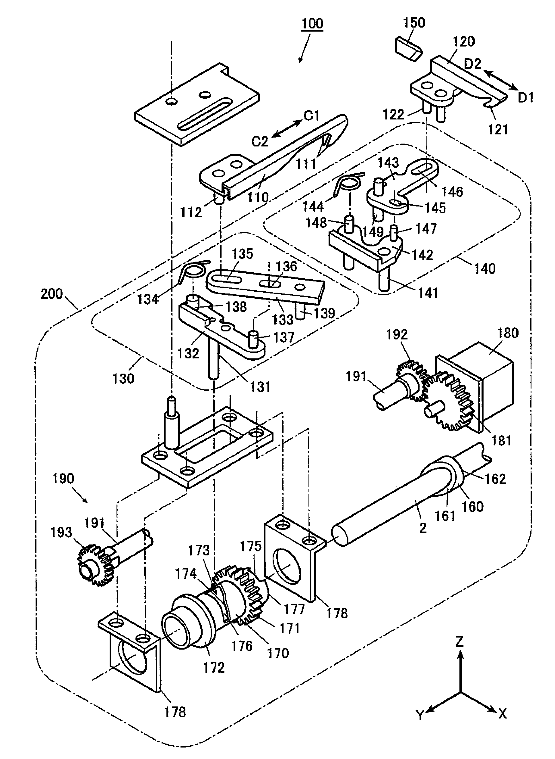
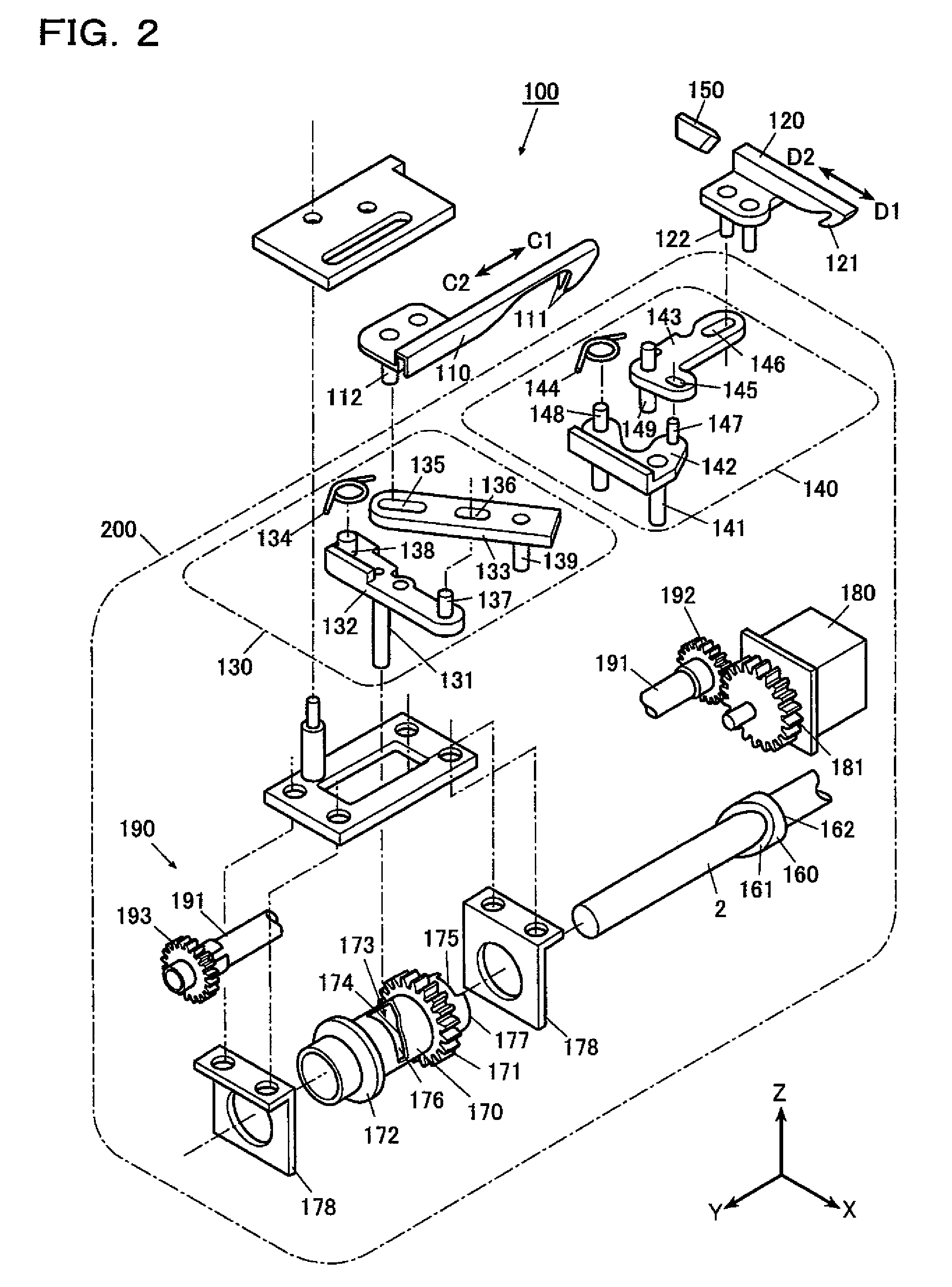
[0060]The best mode for carrying out the invention will be described below in detail with reference to FIGS. 1 to 18. Although various technical preferred restrictions for carrying out the invention are imposed on an embodiment which will be described below, the scope of the invention is not restricted to the following embodiment and examples shown in the drawings. In the embodiment, moreover, it is assumed that a direction of each portion in a sewing machine 1 (which will be described below) is defined based on X, Y and Z axes shown in the respective drawings. In a state in which the sewing machine 1 is disposed on a horizontal plane, a Z-axis direction indicates a vertical direction to be a perpendicular direction, a Y-axis direction indicates a transverse direction which is coincident with a longitudinal direction of an arm portion 11, and an X-axis direction indicates a longitudinal direction which is horizontal and is orthogonal to the Y-axis ...


PUM


Abstract

The thread cutting device of a sewing machine provides a first thread catching member having a first thread catching portion for catching a thread positioned between the horizontal shuttle and the needle hole and carrying out forward and backward movements below the throat plate while the first thread catching portion catches the thread, a second thread catching member having a second thread catching portion for catching the thread laid between the needle hole and the first thread catching portion and guiding the thread caught by the first thread catching member to a fixed blade and to cut the thread by the fixed blade

Description

[0001]The present invention claims priority from Japanese Patent Application No. 2007-106229 filed on Apr. 13, 2007, the entire content of which is incorporated herein by reference.BACKGROUND OF INVENTION[0002]1. Field of the Invention[0003]The present invention relates to a thread cutting device of a sewing machine which serves to guide a thread caught by a thread catching member to a fixed blade and to cut the thread by the fixed blade.[0004]2. Description of the Related Art[0005]Conventionally, a thread cutting device of a sewing machine which serves to cut a thread such as a needle thread or a bobbin thread in the end of a sewing work over a horizontal shuttle (for example, see JP-B-3106472) is provided with a thread catching body 610 provided in a sewing machine bed and serving to receive a power from a lower shaft to be driven by a sewing machine motor, thereby carrying out forward and backward movements (see FIG. 20A). In the forward and backward movements of the thread catch...

Claims


Application Information

Patent Timeline
IPC IPC(8): D05B65/00
CPCD05B65/02D05B69/14
Inventor HANADA, TSUYOSHI
Owner JUKI CORP
Why Eureka
Try Eureka