

Drive apparatus for a multi-shaft extruder rotating in a same direction
- Summary
- Abstract
- Description
- Claims
- Application Information
AI Technical Summary
Benefits of technology
Problems solved by technology
Method used
Image

Examples
Embodiment Construction
[0015] The depicted embodiment is to be understood as illustrative of the invention and not as limiting in any way. It should also be understood that the drawing is not necessarily to scale and that the embodiment is sometimes illustrated by graphic symbols, phantom lines, diagrammatic representations and fragmentary views. In certain instances, details which are not necessary for an understanding of the present invention or which render other details difficult to perceive may have been omitted.
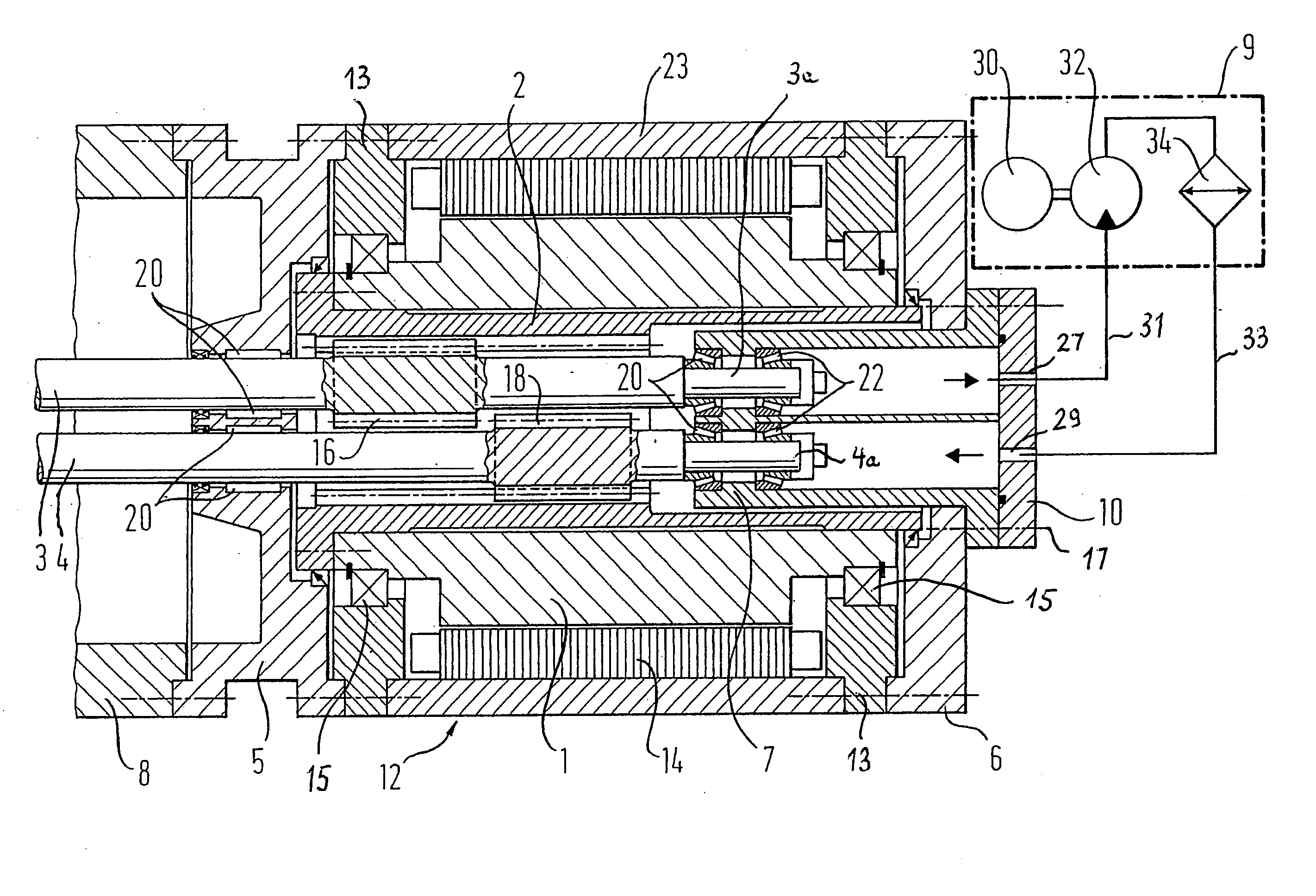
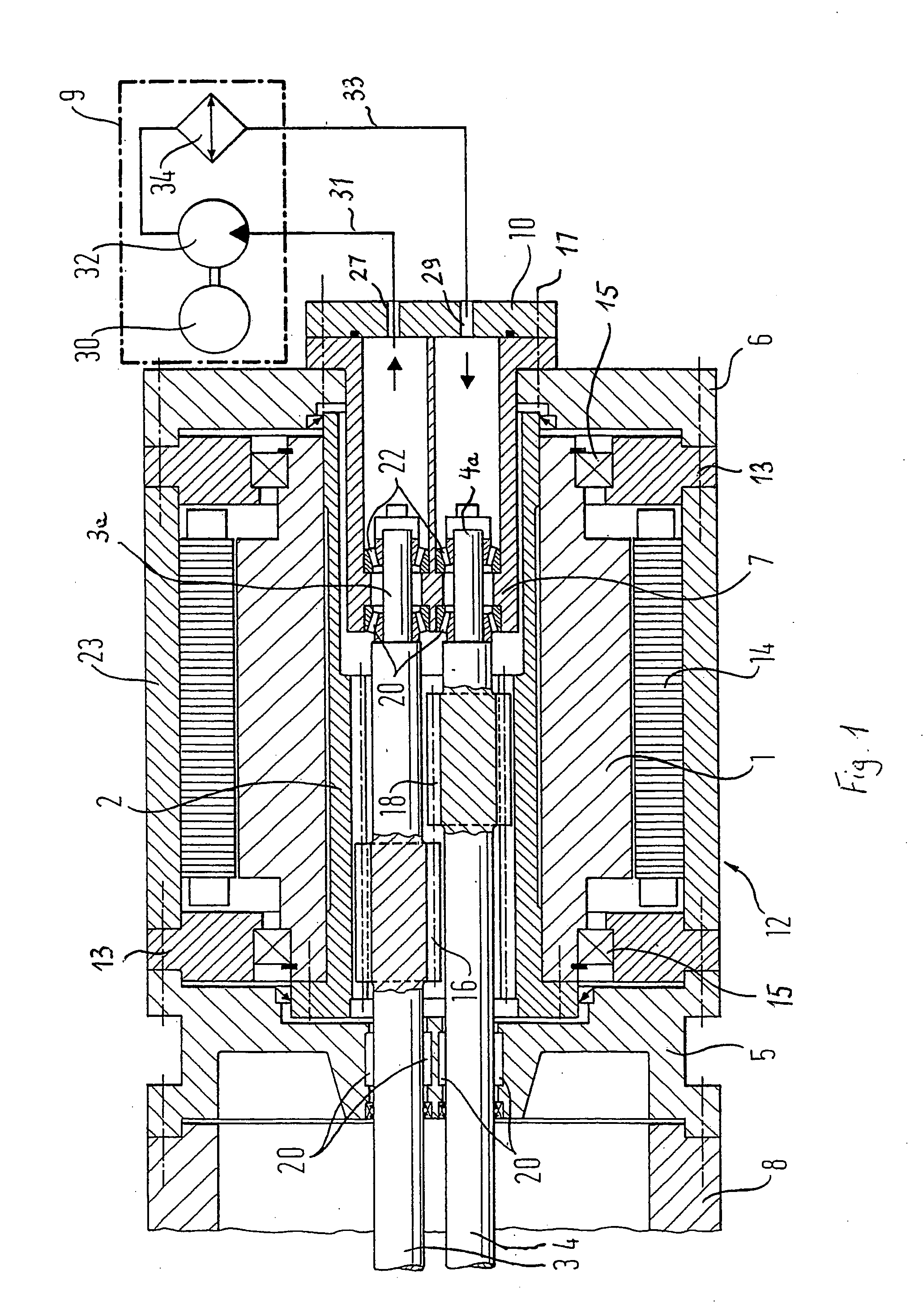
[0016] Turning now to FIG. 1, there is shown a schematic sectional view of a drive apparatus according to the present invention, including a housing 12 for accommodating a drive motor constructed as hollow-shaft motor with a stator 14 and a rotor 1. In the non-limiting example of FIG. 1, the housing 12 is of multi-part configuration and includes a substantially ring-shaped cooling jacket 23 as well as two end walls 13 which are arranged on opposite axial ends of the cooling jacket 23 and con...
PUM
 Abstract
Description
Claims
Application Information