T-fitting manufacturing method and tool

Active Publication Date: 2011-03-24
NIBCO INC
View PDF13 Cites 6 Cited by
  • Summary
  • Abstract
  • Description
  • Claims
  • Application Information

AI Technical Summary

Benefits of technology

The present invention reduces the amount of copper in a T-fitting by from 10% to 12% by providing a punch for forming opposite ends of a copper tube into a T, which includes a tapered or shovel-nose such that the spacing between the ends of the opposed punches is reduced,

Problems solved by technology

In view of the increasing cost of copper, this material, which does not provide

Method used


Image

  • T-fitting manufacturing method and tool
  • T-fitting manufacturing method and tool
  • T-fitting manufacturing method and tool

Examples


Example

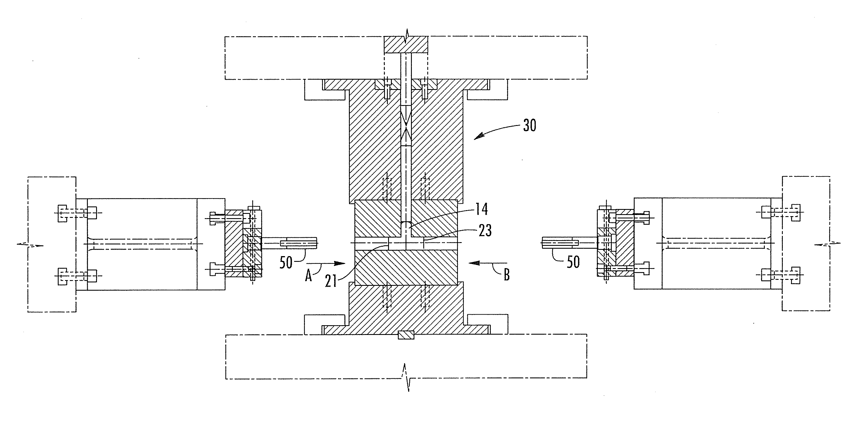
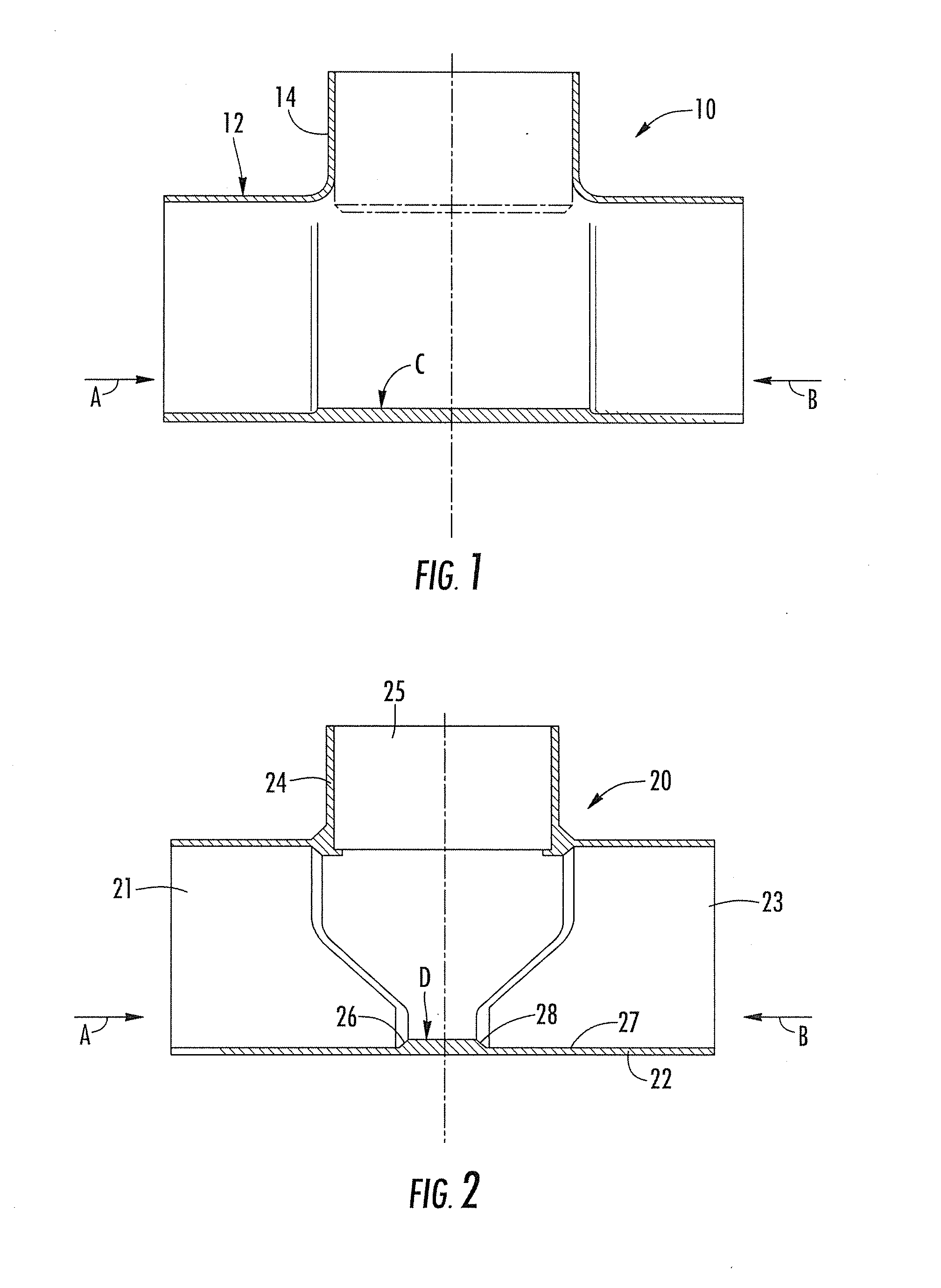
Referring initially to FIG. 1, there is shown a conventional T-fitting 10 in which a copper tube is formed by compressing under water at high pressure (about 10,000 psi) utilizing cylindrical punch noses compressing a straight section of cylindrical copper pipe in opposite directions indicated by arrows A and B in FIGS. 1 and 2. The result is a domed cylindrical orthogonal T-extension 14 (FIG. 12) to the otherwise cylindrical pipe 12. The enclosed end of domed extension 14 is cut in a second step, after which each of the three open ends is sized in a sizing guide to form the finished product. The cylindrical punches are inserted in the pipe in opposite directions as indicated by arrows A and B, however, resulting in a buildup of copper in the area indicated by arrow C in FIG. 1. This extends substantially the width of the of the diameter of the T-section 14. This buildup of copper material provides no additional strength or functional value to the T-fitting 10 and represents a waste...


PUM

PropertyMeasurementUnit
Angleaaaaaaaaaa
Angleaaaaaaaaaa
Angleaaaaaaaaaa

Abstract

A punch for forming opposite ends of a copper tube into a T includes a tapered or shovel-nose such that the spacing between the ends of the opposed punches is reduced, thereby reducing the excess copper remaining in the T once formed. A method of forming the fitting employs the shovel-nose punches in a hydro-forming process to accommodate such results.

Description

BACKGROUND OF THE INVENTIONThe present invention relates to the manufacturing of copper T-fittings.FIG. 1 shows a diagram of prior art T-fittings manufactured by a hydro-forming process utilizing generally cylindrical end punches, as seen in the prior art manufacturing equipment of FIG. 12. The punches move toward one another and engage a copper tube to compress the copper tube to form the orthogonal T-extension. The process includes the subsequent steps of cutting the end of the extending orthogonal section and sizing all three openings of the T for final dimensioning. With prior art processes and tooling, however, a relatively large amount of copper remains in the T at a position opposite the opening of the orthogonal T, as shown by arrow C in FIG. 1. In view of the increasing cost of copper, this material, which does not provide a useful function to the T itself, is an unnecessary cost to the final product.There exists a need, therefore, for a T-fitting design and manufacturing p...

Claims


Application Information

Patent Timeline
IPC IPC(8): B21C37/29B21D39/20F16L41/02
CPCF16L41/021B21D26/037
Inventor SCHLABACH, JOHN W.
Owner NIBCO INC
Why Eureka
Try Eureka