Motor drive apparatus

Active Publication Date: 2005-07-28
PANASONIC SEMICON SOLUTIONS CO LTD
View PDF2 Cites 4 Cited by
  • Summary
  • Abstract
  • Description
  • Claims
  • Application Information

AI Technical Summary

Benefits of technology

[0013] Therefore, an object of the present invention is to provide a motor drive apparatus which has a quick response to a position signal and prevents chattering which occurs in a rotation signal. In addition, another object of the present invention is to prevent a motor drive apparatus which is capable of freely changing the timing at which the rotation signal changes.
[0015] A motor drive apparatus of the present invention comprising: a position detection section for detecting a relative position between motor windings of a plurality of phases and a rotor which are included in the motor to be controlled, and outputting a position signal; a crossing detection section for making a comparison between the position signal and a reference level of the position signal, and outputting a rotation signal which indicates a magnitude relation between the position signal and the reference level; an energization control signal generation section for generating, based on the rotation signal, energization control signals for sequentially energizing the motor windings of a plurality of phases; a pulse width modulation signal generation section for generating a pulse width modulation signal having a predetermined time width; a gate circuit for performing a logical operation on the energization control signals and the pulse width modulation signal; and a plurality of power transistors for supplying power to the motor windings of a plurality of phases based on the energization control signals and output signals of the gate circuit. The crossing detection section includes: a comparator for making a comparison between the position signal and the reference level, and outputting an interim rotation signal which indicates the magnitude relation between the position signal and the reference level; a mask signal generation section for outputting a mask signal over a predetermined mask time from when the magnitude relation between the position signal and the reference level is reversed; and an output signal holding section for outputting the interim rotation signal as the rotation signal when the mask signal is not outputted, holding the interim rotation signal therein when an output of the mask signal is started, and outputting the signal held therein as the rotation signal when the mask signal is being outputted. According to such a motor drive apparatus, when chattering occurs in the rotation signal, a mask signal is generated so that the rotation signal does not change, and thus chattering which occurs in the rotation signal can be prevented without reducing a response to the position signal.
[0016] In this case, the crossing detection section may further include an edge signal generation section for outputting an edge signal when the interim rotation signal is changed, and the mask signal generation section may output the mask signal over the mask time from when the edge signal is outputted. By this, the crossing detection section can be easily configured.
[0019] The mask signal generation section may generate the mask signal over a predetermined period of time commencing from before the pulse width modulation signal is outputted and ending after the pulse width modulation signal is outputted. By this, even in the case where PWM noise is included in the position signal, chattering which occurs in the rotation signal can be prevented.

Problems solved by technology

Here, the noise generated in the motor drive apparatus may interfere the position signal and chattering may occur in the rotation signal.
The above-described conventional motor drive apparatuses, however, have the following problems.
This causes a delay in the output of the rotation signal, and as a result, the response to the detected position signal is reduced.
In particular, in a high-speed rotation motor, a slight delay time may cause a large phase delay and thus a reduction in response leads to a big problem.
Therefore, in the case where the position signal changes slowly, the delay time becomes longer, resulting in a delay in the output of the rotation signal.
Further, in the case where the hysteresis width is smaller than the level of noise, chattering occurs in the rotation signal, and thus the level of noise needs to be pre-estimated when determining the hysteresis width of the comparator.

Method used


Image

  • Motor drive apparatus
  • Motor drive apparatus
  • Motor drive apparatus

Examples


first embodiment

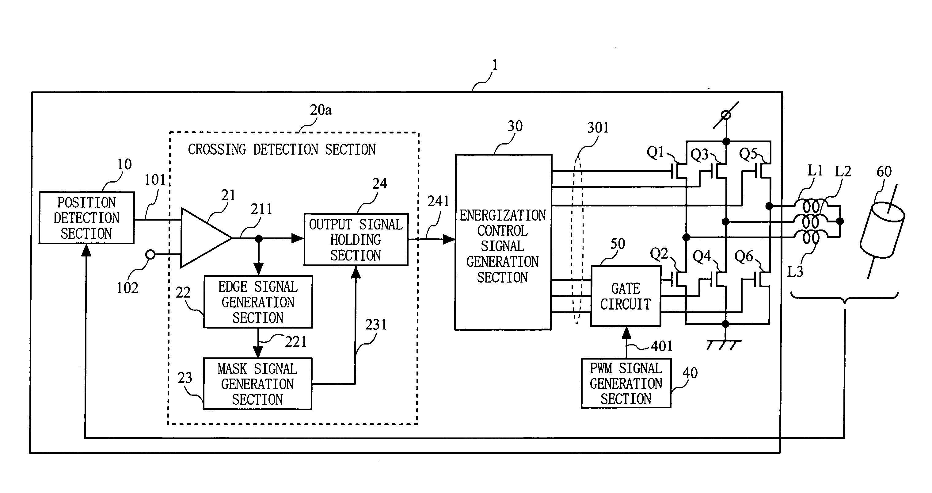
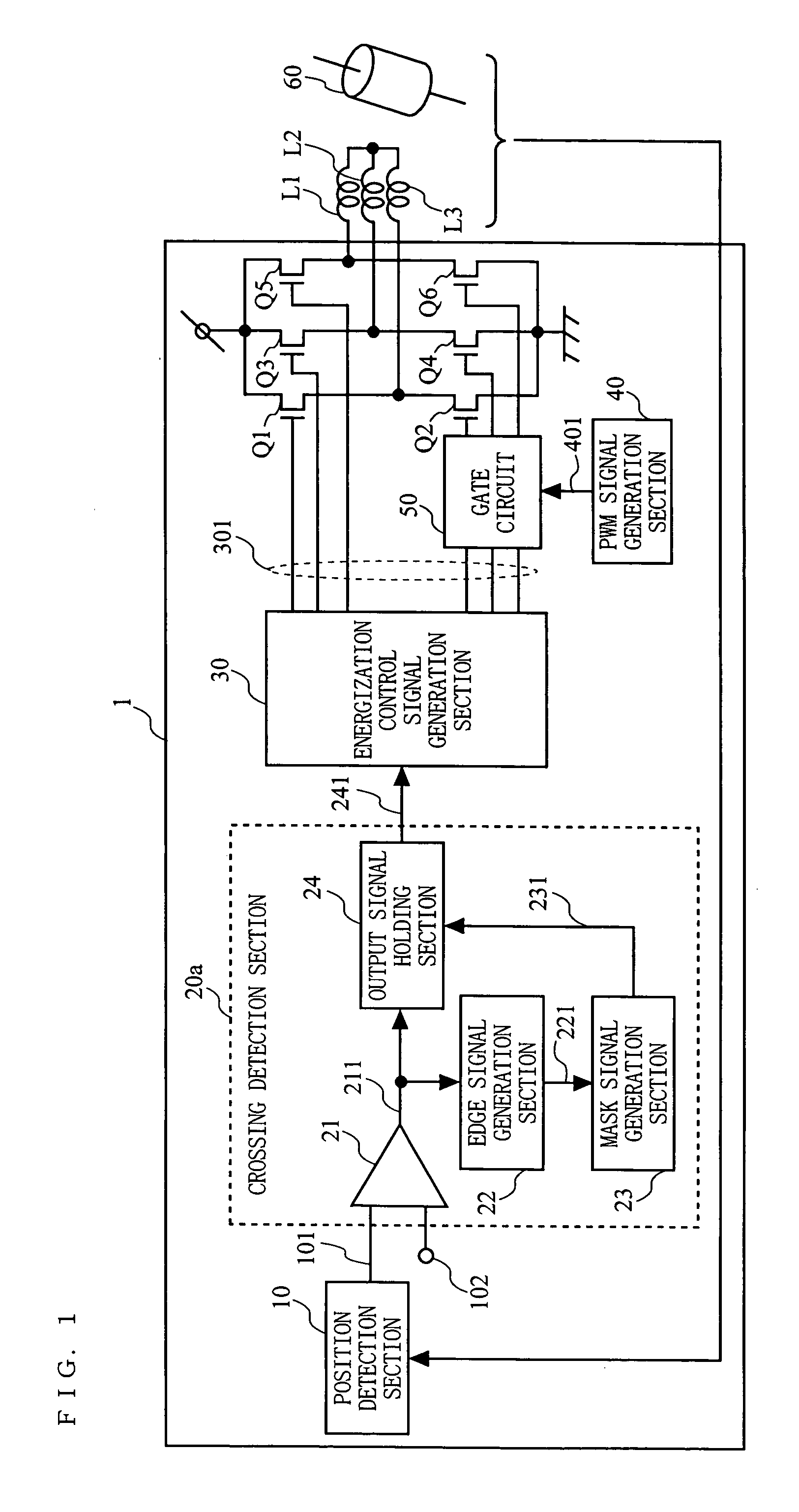
[0031]FIG. 1 is a diagram showing the configuration of a motor drive apparatus according to a first embodiment of the present invention. A motor drive apparatus 1 shown in FIG. 1 includes a position detection section 10; a crossing detection section 20a, an energization control signal generation section 30; a PWM signal generation section 40; a gate circuit 50; and power transistors Q1 to Q6. The motor drive apparatus 1 continuously controls the rotation of a motor having motor windings L1 to L3 of a plurality of phases and a rotor 60.

[0032] In FIG. 1, the position detection section 10 detects the relative position between the motor windings L1 to L3 and the rotor 60 and outputs a position signal 101 which indicates the result of the detection. The position signal 101 is inputted to the crossing detection section 20a. In addition to the position signal 101, a reference signal 102 which indicates the reference level of the position signal 101 is inputted to the crossing detection se...

second embodiment

[0041]FIG. 5 is a diagram showing the configuration of a motor drive apparatus according to a second embodiment of the present invention. A motor drive apparatus 2 shown in FIG. 5 is different from the motor drive apparatus 1 (shown in FIG. 1) according to the first embodiment in that the crossing detection section 20a is replaced with a crossing detection section 20b. The crossing detection section 20b is such that an output signal delay section 27 is additionally included in the crossing detection section 20a. Note that among the components of the present embodiment, the same components as those of the first embodiment are designated by the same reference numerals, and the description thereof will be omitted.

[0042] The output signal delay section 27 is provided between the output signal holding section 24 and the energization control signal generation section 30 and delays the rotation signal 241 outputted from the output signal holding section 24 by a predetermined delay time. T...

third embodiment

[0046]FIG. 7 is a diagram showing the configuration of a motor drive apparatus according to a third embodiment of the present invention. A motor drive apparatus 3 shown in FIG. 7 is different from the motor drive apparatus 2 (shown in FIG. 5) according to the second embodiment in that the crossing detection section 20b is replaced with a crossing detection section 20c. The crossing detection section 20c is such that the mask signal generation section 23 of the crossing detection section 20b is replaced with a mask signal generation section 28. Note that among the components of the present embodiment, the same components as those of the second embodiment are designated by the same reference numerals, and the description thereof will be omitted.

[0047] As in the case with the mask signal generation section 23, the mask signal generation section 28 outputs a mask signal 281 over a predetermined mask time from when an edge signal 221 is outputted. In addition, the mask signal generation...


PUM


Abstract

A position detection section 10 outputs a position signal 101 indicating the relative position between motor windings L1 to L3 and a rotor 60. A crossing detection section 20a outputs a rotation signal 241 indicating the magnitude relation between the position signal 101 and a reference signal 102. An energization control signal generation section 30 generates, based on the rotation signal 241, energization control signals 301 for the motor windings L1 to L3. An edge signal 221 is outputted when the magnitude relation of the two signals is reversed, and a mask signal 231 is outputted over a predetermined period of time from when the edge signal 221 is outputted. While the mask signal 231 is being outputted, the crossing detection section 20a continuously outputs, as the rotation signal 241, a comparison result signal 211 which had been inputted before the mask signal 231 was outputted.

Description

BACKGROUND OF THE INVENTION [0001] 1. Field of the Invention [0002] The present invention relates to a motor drive apparatus, and more particularly to a motor drive apparatus which detects the relative position between motor windings and a rotor and continuously controls the rotation of a motor. [0003] 2. Description of the Background Art [0004] Motor drive apparatuses obtain a position signal which indicates the relative position between motor windings and a rotor, obtain a rotation signal which indicates the magnitude relation between the position signal and the reference value of the position signal, and continuously control the power to be supplied to the motor based on the rotation signal. Here, the noise generated in the motor drive apparatus may interfere the position signal and chattering may occur in the rotation signal. In order to prevent chattering which occurs in the rotation signal, conventional motor drive apparatuses employ a method of eliminating noise which is cont...

Claims


Application Information

Patent Timeline
IPC IPC(8): H02P6/08H02P6/06H02P6/16
CPCH02P6/182H02P6/16
Inventor MURAKAMI, MAKI
Owner PANASONIC SEMICON SOLUTIONS CO LTD
Why Eureka
Try Eureka