Filter for plastic material

Active Publication Date: 2016-11-03
FIMIC SRL
View PDF32 Cites 7 Cited by
  • Summary
  • Abstract
  • Description
  • Claims
  • Application Information

AI Technical Summary

Benefits of technology

The present invention provides a filter for plastic material that can provide excellent filtration in a short time, requires a low initial investment, keeps the physical characteristics of the material obtained, easily maintains, provides higher quality for materials that could not be filtered twice, produces less waste, and is small. The filter has a hollow body with at least one inlet and at least one outlet, and a drive shaft that rotates scrapers. The filter has at least two filtration devices arranged in series, with the scrapers rotated by the same drive shaft. The filter has a discharge channel for removing the dirty material, which can be connected to the outside through a window. The channels are fitted with valves for opening and closing them. The pressure for the exit of the dirty material is provided directly by the material to be filtered. These and other objects are all achieved by the filter for plastic material, in accordance with the attached claims.

Problems solved by technology

However, the pressures and the length of the entire path, the first machine-pump-second machine, are so high that they greatly deteriorate the plastic material.
We should keep in mind also that the use of two machines, besides being very expensive, presupposes substantial costs for the replacement of the filters, which are generally changed, even if this is not indispensable, simultaneously on both machines.
It is therefore clear that whatever filtration method is followed, with two passes, or in a single and continuous sequence on two machines, the costs to achieve optimal quality with minimum residue is costly especially in terms of time, of the financial costs for spare parts and the poorer performance characteristics of the material obtained.

Method used


Image

  • Filter for plastic material
  • Filter for plastic material
  • Filter for plastic material

Examples


Embodiment Construction

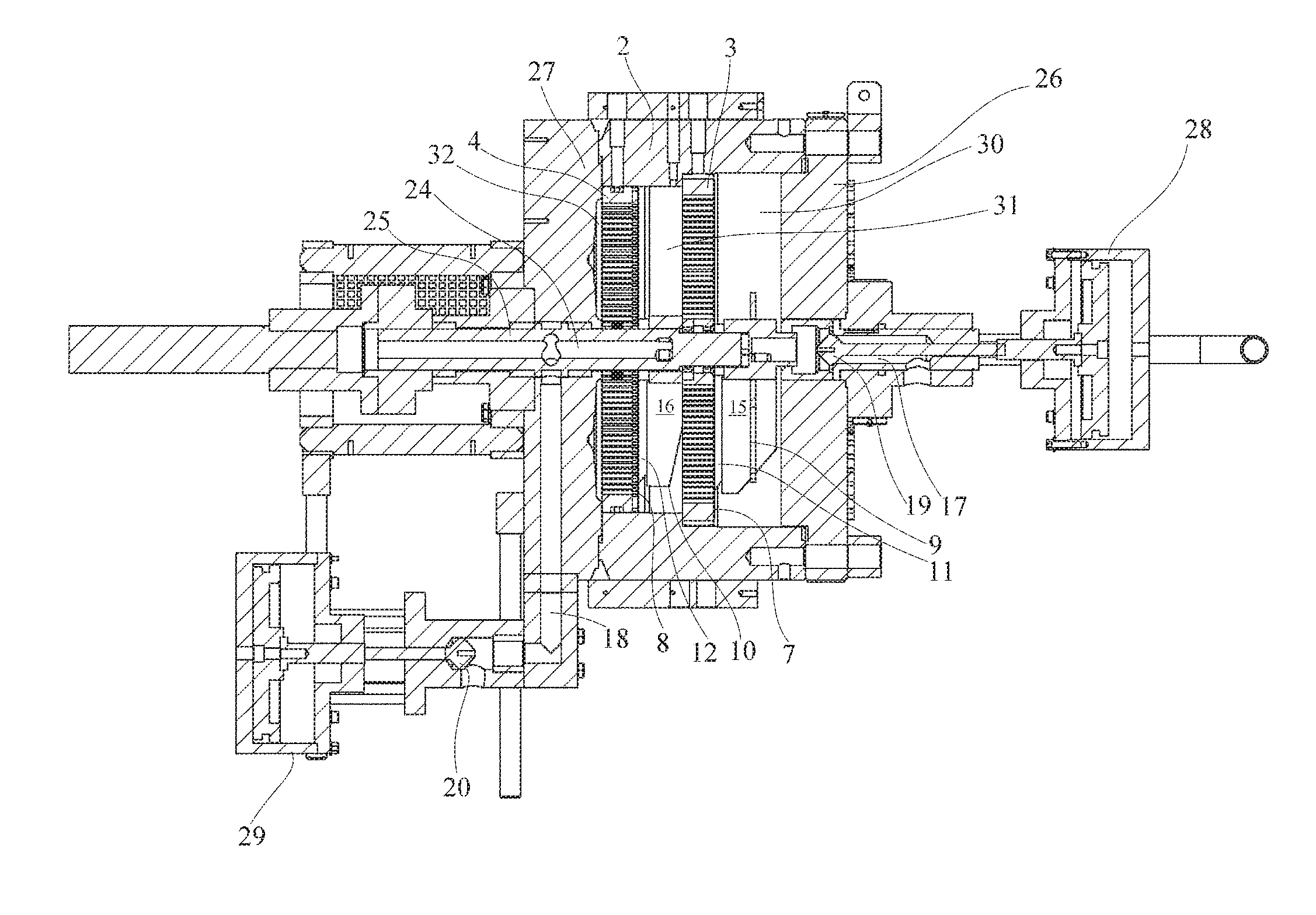
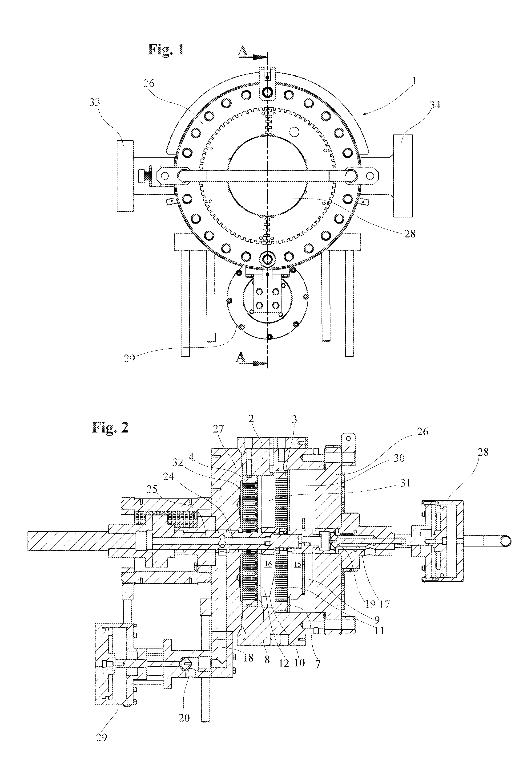
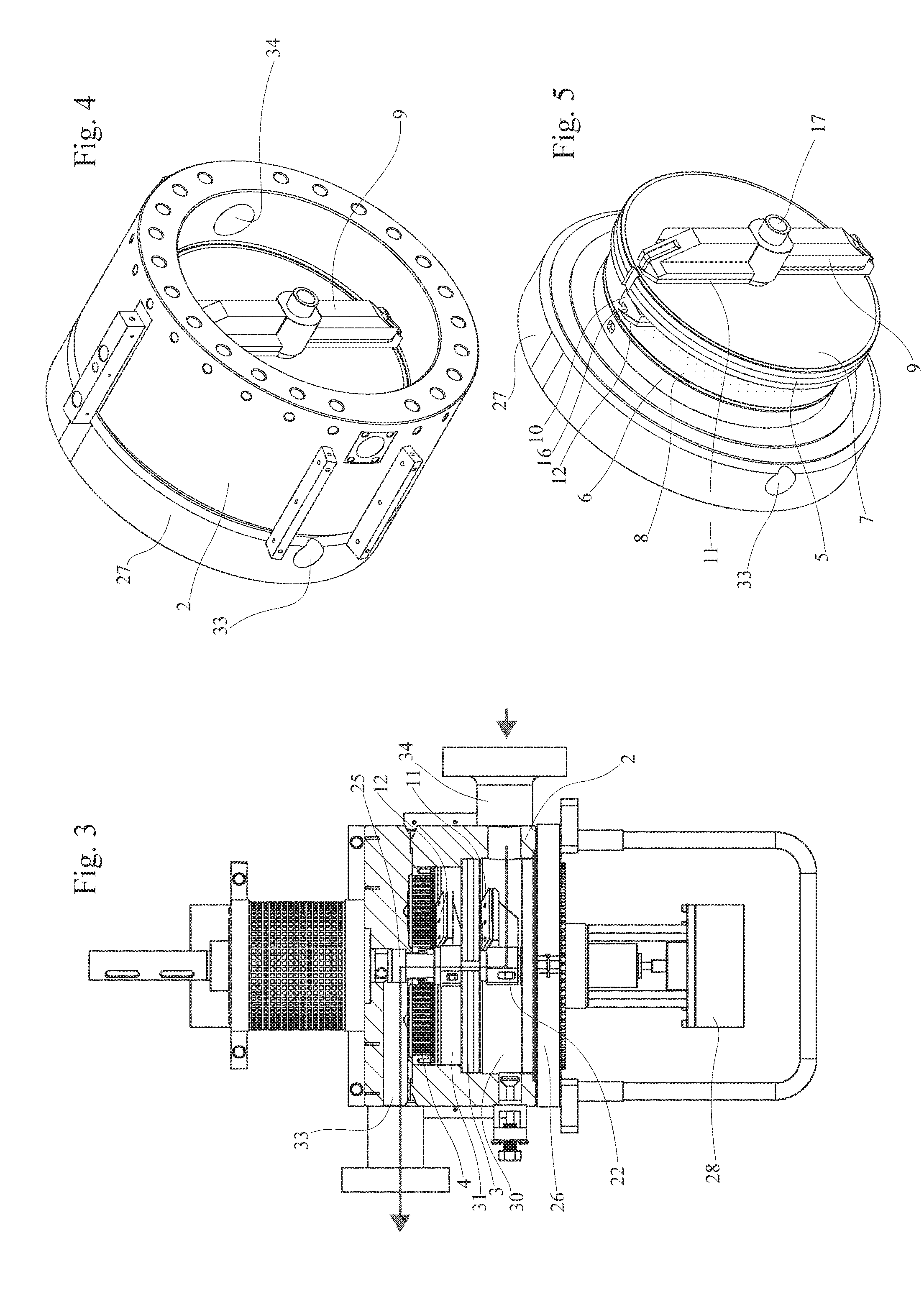
[0055]With reference to the figures, the filtration device 1 is basically composed of a hollow body 2 within which are housed a first filtration device 3 and a second filtration device 4.

[0056]Said first and said second filtration devices 3, 4, are arranged in sequence with a different filtration quality, so that the first filtering device 3, positioned upstream of the second filtration device 4 retains the largest pieces of dirt that in the molten plastic material, while the filtration device 4, which is downstream, retains the smallest dirt particles in the molten plastic material to be filtered.

[0057]Each of said filter devices 3 and 4 is composed of a perforated disc 5, 6, with an appropriately sized support to withstand the mechanical stresses, having a basically circular cross-section and that rests in a suitable housing within the hollow body 2.

[0058]Said perforated disc 5, 6 is likely to be a very thick perforated plate, which remains fixed with respect to the hollow body 2 ...


PUM

PropertyMeasurementUnit
Grain sizeaaaaaaaaaa
Pressureaaaaaaaaaa
Diameteraaaaaaaaaa

Abstract

What is presented is a filter for plastic material, in particular a device that filters recycled plastic material, to clean it of extraneous bodies and foreign elements by means of several filtration units within a single body.

Description

CROSS-REFERENCE TO RELATED APPLICATIONS[0001]This application claims the benefit of Italian Patent Application IT UB2015 / 0321, filed on Apr. 30, 2015, and incorporated herein by reference.STATEMENT REGARDING FEDERALLY SPONSORED RESEARCH AND DEVELOPMENT[0002]Not Applicable.FIELD OF THE INVENTION[0003]The object of this invention relates to a filter for plastic material, in particular a device that filters plastic recycling material to clean it of foreign bodies and elements.DISCUSSION OF RELATED ART[0004]The technique is well known whereby the plastic material to be cleaned is heated to the point of melting to become a fluid so that it can be pushed under pressure inside a cleaning machine equipped with a filter for retaining all the solid parts, which are bodies and elements that are extraneous to the plastic material.[0005]However at present the degree of purity required is always higher. Therefore there is a trend in the cleaning procedure towards subjecting the plastic material t...

Claims


Application Information

Patent Timeline
IPC IPC(8): B01D29/05B01D29/58B01D29/64B29B17/02B29C48/693B29C48/92
CPCB01D29/05B29B17/02B29B2017/0217B01D29/6476B01D29/58B29C48/92B29C48/2545B29C48/2735B29C48/693B29C2948/92019B29B7/58
Inventor CANAIA, ERICA
Owner FIMIC SRL
Why Eureka
Try Eureka