System and method for turbo compressor recirculation valve control

a turbo compressor and recirculation valve technology, applied in the field of turbo compressor recirculation valve control system and method, can solve the problems of affecting the longevity of the nvh and compressor, the speed of the turbocharger to drop rapidly, and the associated temporary pressure drop, so as to reduce the effect of improve control logic, and effectively prevent surge and boost pressure spikes

Active Publication Date: 2009-05-05
DELPHI TECH IP LTD
View PDF24 Cites 51 Cited by
  • Summary
  • Abstract
  • Description
  • Claims
  • Application Information

AI Technical Summary

Benefits of technology

[0005]The present invention provides for improved control logic for opening and closing a compressor recirculation valve. Embodiments of the invention will be inherently more stable since they will use predictive values available from a conventional torque-based engine management system (EMS). Additionally, since the decision logic uses predictive values from the EMS, the time for commanding the valve to open can be advanced relative to conventional approaches, which can more effectively prevent surge and boost pressure spikes or minimize its effects. Embodiments of the invention will also be significantly easier to implement as they will utilize compressor characteristics data (map) typically provided by turbo-charger manufacturers. Moreover, embodiments of the invention will automatically incorporate altitude compensation.

Problems solved by technology

The pressure spike is caused by the column of air being decelerated due to the sudden blockage by the throttle valve, while the compressor at the other end of the volume does not allow for any pressure dispersion.
Compressor operation in the surge region is unstable because the pressure ratio is too large for the small flow rate, causing flow reversal and an associated temporary pressure drop.
However, the cycling between these opposite processes typically happens at a high frequency causing unpleasant NVH and compressor longevity issues.
Furthermore, surge can cause the turbo-charger speed to drop rapidly, which may impair responsiveness on a subsequent tip-in.
However, one disadvantage of such an approach is a lag time after commanding the recirculation valve to open until the time when the valve actually opens and begins to have the desired effect.

Method used


Image

  • System and method for turbo compressor recirculation valve control
  • System and method for turbo compressor recirculation valve control
  • System and method for turbo compressor recirculation valve control

Examples


Embodiment Construction

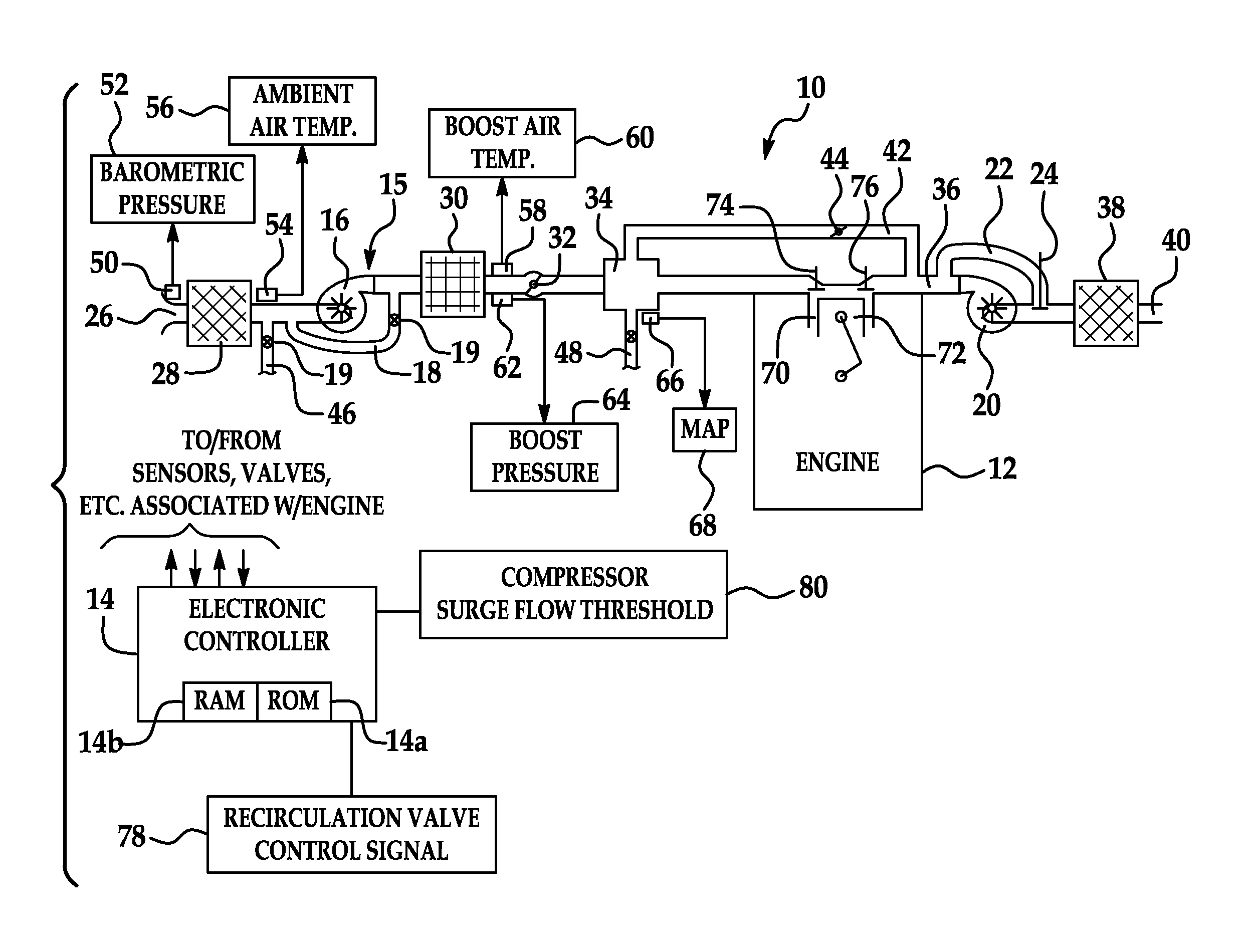
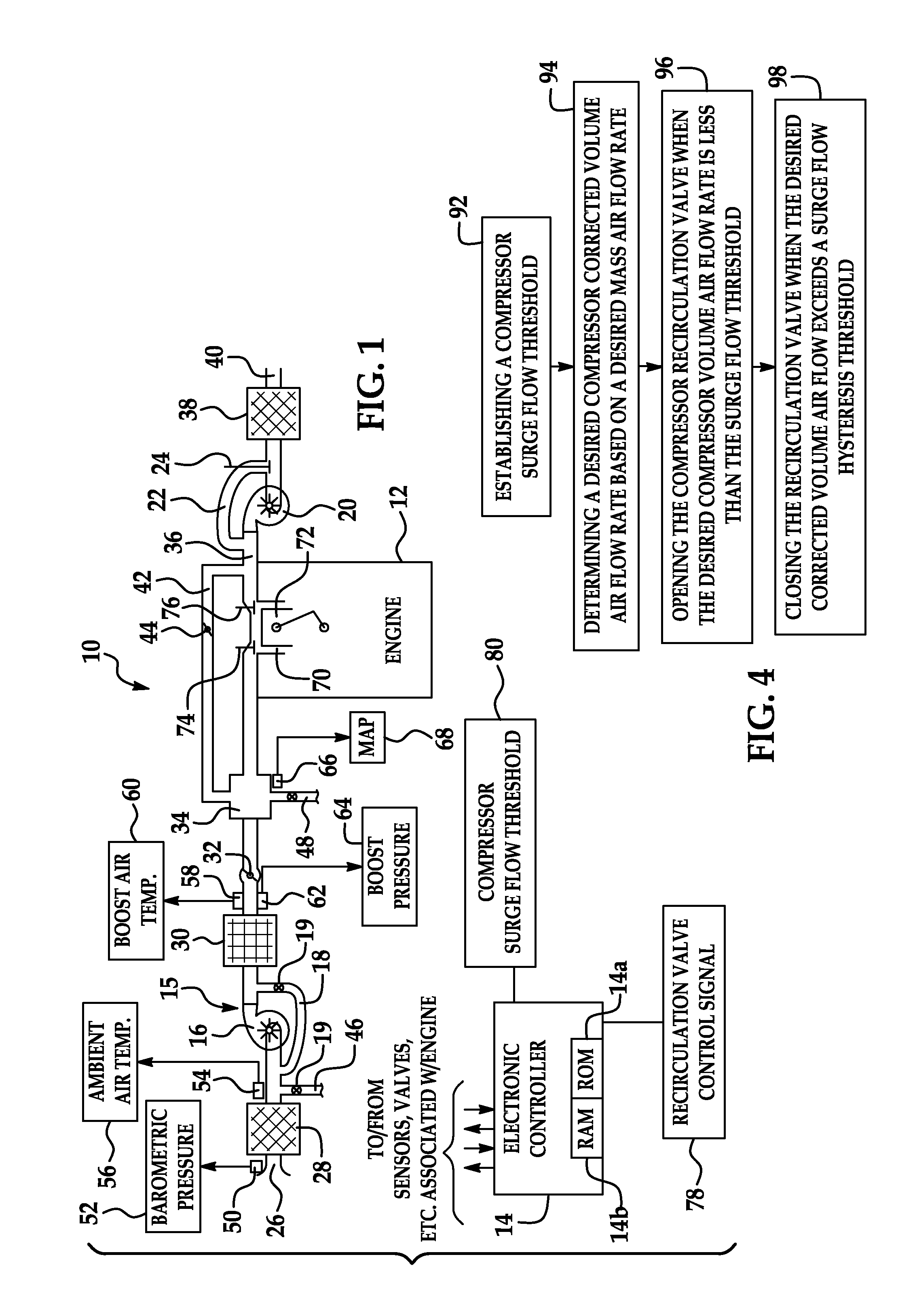
[0014]Referring now to the drawings wherein like reference numerals are used to identify identical components in the various views, FIG. 1 is a diagrammatic view of a turbo-charged internal combustion engine system 10 configured in accordance with the present invention. The system 10 includes an internal combustion engine 12 controlled by an electronic engine controller 14. Engine 12 may be a spark-ignition engine that includes a number of base engine components, sensing devices, output systems and devices, and a control system. Alternatively, the present invention may be used with compression-ignition engines, such as diesel or the like.

[0015]Generally, electronic controller 14 is configured via suitable programming to contain various software algorithms and calibrations, electrically connected and responsive to a plurality of engine and vehicle sensors, and operably connected to a plurality of output devices. Controller 14 includes at least one microprocessor or other processing u...


PUM


Abstract

A system and method for controlling a compressor recirculation valve involves establishing a compressor surge flow threshold expressed in terms of a compressor corrected volume air flow rate. A torque-based engine management system computes a desired mass air flow rate in accordance with a torque request and other operating / predetermined data. The desired mass air flow rate is converted into a desired, corrected volume air flow rate, which is then compared to the compressor surge flow threshold. The controller is configured to open the valve when the desired corrected volume air flow rate is less than the compressor surge flow threshold. A hysteresis function is implemented by providing a surge flow hysteresis threshold that is offset from and greater than the initial compressor surge flow threshold. The controller is configured to close the recirculation valve when the desired corrected volume air flow rate becomes greater than the surge flow hysteresis threshold.

Description

TECHNICAL FIELD[0001]The present invention relates to a system and method for turbo compressor recirculation valve control.BACK GROUND OF THE INVENTION[0002]turbo-charged internal combustion engine includes additional components and physical processes in both the intake and exhaust stream. On the intake side of the engine, a centrifugal compressor and intercooler are provided and are located between the air cleaner and a throttle valve. There is typically a recirculation path that is controlled by a recirculation valve coupled between the outlet and the inlet of the compressor. The purpose of the recirculation valve is that it can be opened during tip-out (i.e., where an operator of an automotive vehicle lifts off the acceleration pedal causing the throttle valve to close). The opening of the recirculation valve is intended to avoid compressor surge and large boost pressure spikes that would otherwise occur in the volume between the compressor and the throttle. The pressure spike is...

Claims


Application Information

Patent Timeline
Patent Type & Authority Patents(United States)
IPC IPC(8): F02B37/00G06F19/00
CPCF02B37/16F02B37/18Y02T10/144Y02T10/12
Inventor MULLER, MARTIN
Owner DELPHI TECH IP LTD
Why Eureka
Try Eureka