Metal Printer

a 3d printer and metal technology, applied in the field of metal printers, can solve the problems of limiting the application of laser sintering technology, neither amenable nor economic for low-volume manufacturing, etc., and achieve the effects of reducing maintenance requirements, reducing maintenance requirements, and maintaining cleanliness and/or transparency of windows

Inactive Publication Date: 2016-11-03
BRIGANTE AVIATION
View PDF6 Cites 23 Cited by
  • Summary
  • Abstract
  • Description
  • Claims
  • Application Information

AI Technical Summary

Benefits of technology

[0011]In an example embodiment, the laser head is arranged to be repositioned in use. In this way, the laser head may be arranged, for example, a distance from and / or an angle to a filler material and / or a substrate. In this way, the laser head may be arranged at, for example, an optimum and / or a predetermined distance from and / or an optimum and / or predetermined to a filler material and / or a substrate. In this way, the laser head may be arranged to deliver a laser pulse to, for example, a position on a filler material delivered by the 3D printer head and / or a substrate, a plurality of positions on a filler material delivered by the 3D printer head and / or a substrate. For example, the laser head may translate in one, two or three orthogonal dimensions and / or rotate about one, two or three orthogonal axes. In this way, a position and / or orientation of the laser head may be optimised to deliver a laser pulse to a filler material and / or substrate e.g. a laser pulse shape may be maintained while printing a 3D component. In contrast, a fixed laser head in which a position and / or orientation of the fixed laser head are / is fixed will compromise delivery of a laser pulse to a filler material, since a laser pulse shape, for example, will change while printing a 3D component.
[0039]In an example embodiment, the controller is arranged to control a laser shutter. In an example embodiment, the controller is arranged to control a laser shutter, wherein the laser shutter is arrangeable to isolate the laser head from the 3D printer head. In an example embodiment, the controller is arranged to control a laser shutter, wherein the laser shutter is arrangeable to isolate the laser head from the 3D printer head, and wherein the controller is further arranged to control the laser shutter to open according to a timing of a laser pulse delivered by the laser head. In an example embodiment, the controller is arranged to control a laser shutter, wherein the laser shutter is arrangeable to isolate the laser head from the 3D printer head, and wherein the controller is further arranged to control the laser shutter to close according to a timing of a laser pulse delivered by the laser head. In this way, filler material vapour and / or sputter are isolated from for example a window of the laser head through which a laser pulse is delivered. In this way, a cleanliness and / or transparency of the window is maintained or degradation minimized, thereby reducing maintenance requirements.

Problems solved by technology

However, these manufacturing methods are typically multi-step or require significant tooling and thus are generally neither amenable nor economic for low-volume manufacturing, such as for prototype or custom components.
However, the rate, scale, resolution, cost, complexity and material options may limit the application of this laser sintering technique.

Method used


Image

  • Metal Printer
  • Metal Printer
  • Metal Printer

Examples


Embodiment Construction

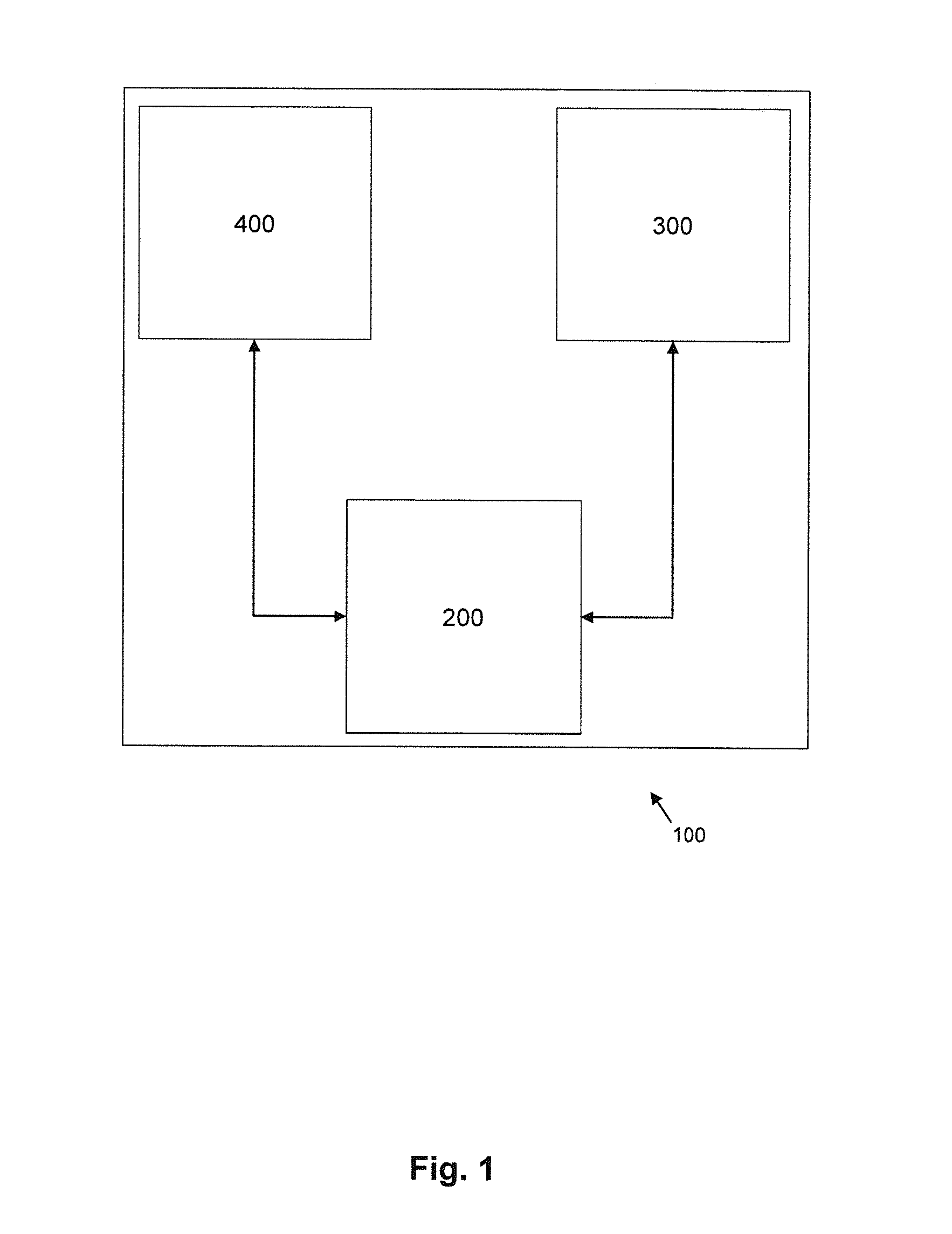
[0074]FIG. 1 shows a schematic view of a 3D printer assembly 100 according to an example embodiment. A laser head 400 and a 3D printer head 300 are coupled to a controller 200. For example, laser head 400 is communicatively and / or optically and / or mechanically coupled to controller 200 and 3D printer head 300 is communicatively coupled to controller 200, in which a communicative coupling may be uni-directional or bi-directional. Further, laser head 400 may be coupled to 3D printer head 300 (not shown). For example, laser head 400 may be communicatively and / or optically and / or mechanically coupled to 3D printer head 300, in which a communicative coupling may be uni-directional or bi-directional.

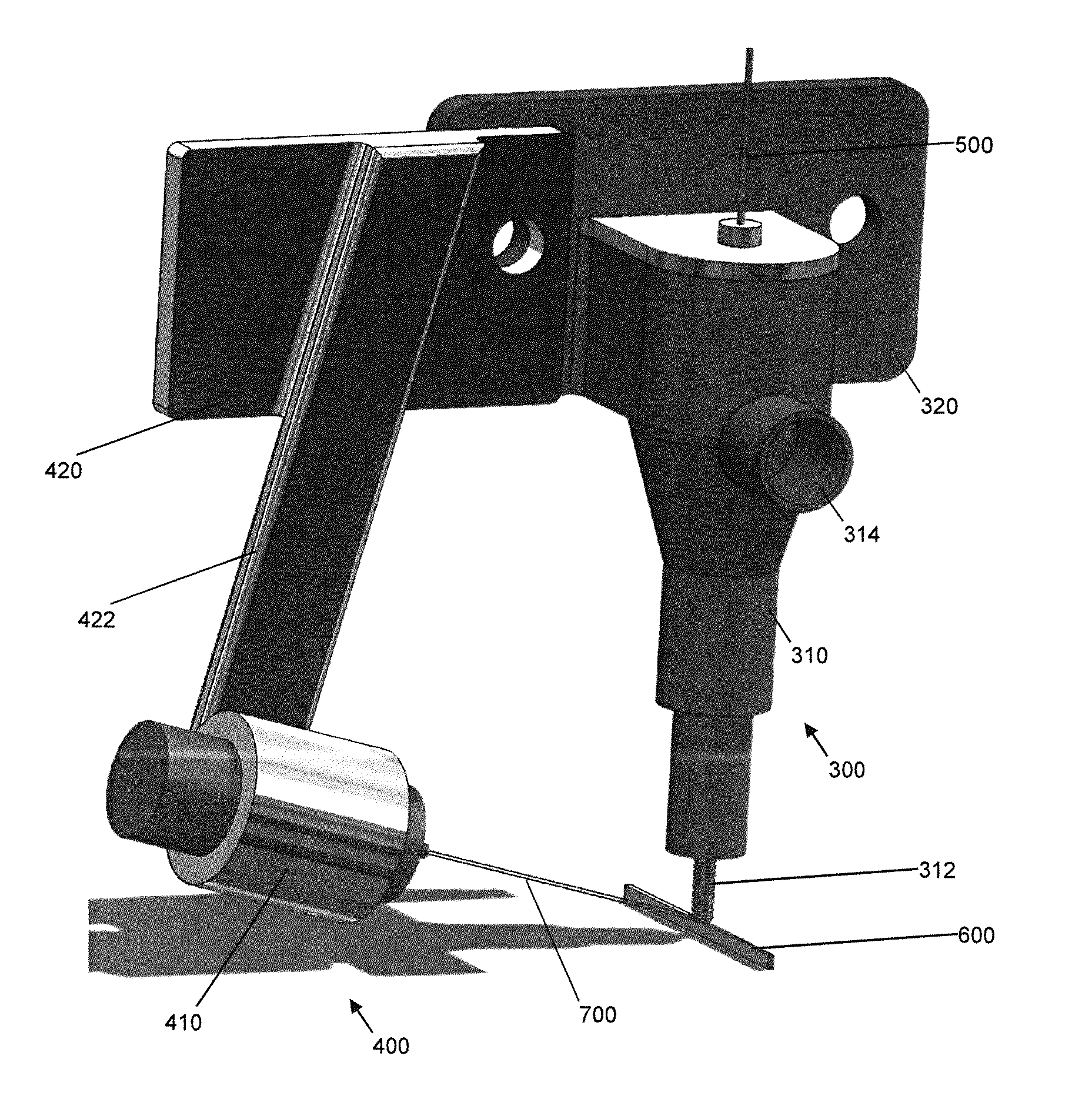
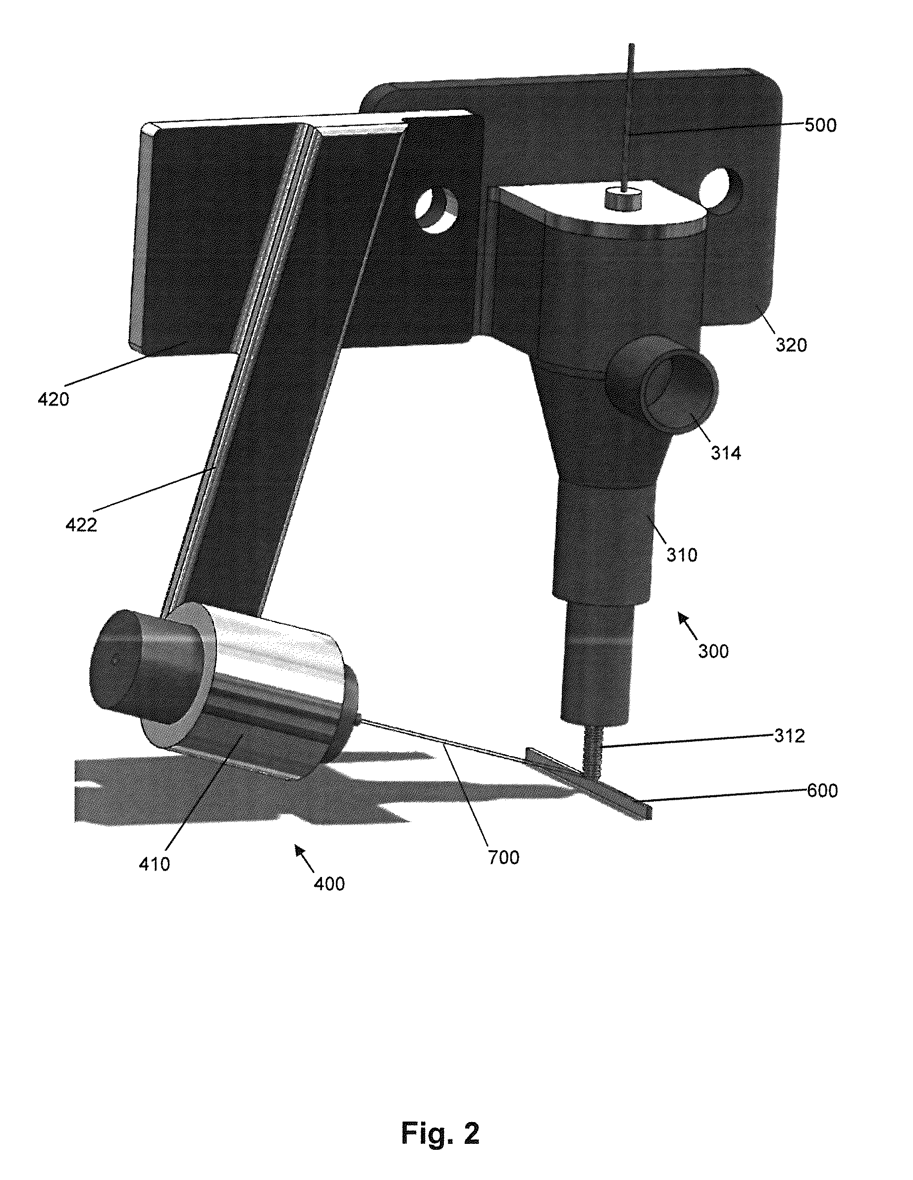
[0075]An example embodiment of a 3D printer assembly 100 is now described with reference to FIGS. 2-8. This example embodiment provides an open head for printing of a 3D component from a filler material.

[0076]FIGS. 2-4 show a schematic perspective view, a schematic, partially-transparent persp...


PUM

PropertyMeasurementUnit
volumeaaaaaaaaaa
energyaaaaaaaaaa
energyaaaaaaaaaa

Abstract

A 3 dimensional, 3D, printer assembly for in use printing a 3D component from a filler material, the 3D printer assembly comprising: a 3D printer head arranged to in use deliver the filler material; a laser head for a laser arranged to in use deliver a laser pulse to the filler material; and a controller arranged to control the printer head and the laser head to in use print the 3D component.

Description

FIELD OF THE INVENTION[0001]The present invention relates to 3D printer assemblies, and to related methods of use of 3D printer assemblies, particularly for use in pulsed-laser 3D printing of metals.BACKGROUND TO THE INVENTION[0002]Engineered components for machinery are typically manufactured by machining or fabricating metal stock, castings or sintered parts. However, these manufacturing methods are typically multi-step or require significant tooling and thus are generally neither amenable nor economic for low-volume manufacturing, such as for prototype or custom components.[0003]Laser sintering of metallic powders has been developed as an alternative manufacturing method for such components. However, the rate, scale, resolution, cost, complexity and material options may limit the application of this laser sintering technique.[0004]Example embodiments of the present invention aim to address at least one of the issues identified above, or related issues.SUMMARY OF THE INVENTION[000...

Claims


Application Information

Patent Timeline
Patent Type & Authority Applications(United States)
IPC IPC(8): B23K26/342B23K26/0622B23K26/144
CPCB23K26/342B23K26/0622B23K26/144B23K26/14B29C70/882B33Y10/00B33Y30/00Y02P10/25B22F12/53B22F12/70B22F10/36B22F10/25B22F12/43B22F10/322
Inventor DUTTON, MICHAEL JOSEPH
Owner BRIGANTE AVIATION
Why Eureka
Try Eureka