LED lighting device and system, and reset button arrangement method

Active Publication Date: 2016-11-03
SENGLED OPTOELECTRONICS
View PDF2 Cites 0 Cited by
  • Summary
  • Abstract
  • Description
  • Claims
  • Application Information

AI Technical Summary

Benefits of technology

LED intelligent lighting system using wireless smart terminals such as laptops, tablets, phones, and smartwatches to connect to the Internet through an LED lighting device with wireless functions. The wireless connection allows the smart terminals to access the Internet without needing a separate network. The LED lighting device has a reset button that can be easily accessed through a bump on the side of the lamp shell. The reset button can be pressed to reset the LED lighting device back to factory settings or when the wireless router function needs to be recovered. The reset button does not affect the appearance of the LED lighting device and is always safe and reliable.

Problems solved by technology

However, when an LED lighting device with a control function is used, sometimes the LED lighting device needs to be reset.
For example, when performance of the LED lighting device is unstable, or the LED lighting device is down, or password of the LED lighting device is forgotten, or factory parameters need to be reset, the LED lighting device needs to be restarted.
If a reset button is not installed, when the LED lighting device has problems or one of the above situations occur, the LED lighting device needs to be sent back to the manufacturer for repair or replacement, resulting in waste of resources and inconvenience.
However, because operations for the reset button need to be performed at a state when the LED lighting device is powered on, and the LED lighting device is often installed on a wall or on top of a wall, the operations are often hard to perform.
Sometimes, due to a special structure of the installation location, the reset button may not be easily reachable, resulting in failure or difficulty in using the reset function.

Method used


Image

  • LED lighting device and system, and reset button arrangement method
  • LED lighting device and system, and reset button arrangement method
  • LED lighting device and system, and reset button arrangement method

Examples


Embodiment Construction

[0018]Reference will now be made in detail to exemplary embodiments of the disclosure, which are illustrated in the accompanying drawings. Wherever possible, the same reference numbers will be used throughout the drawings to refer to the same or like parts.

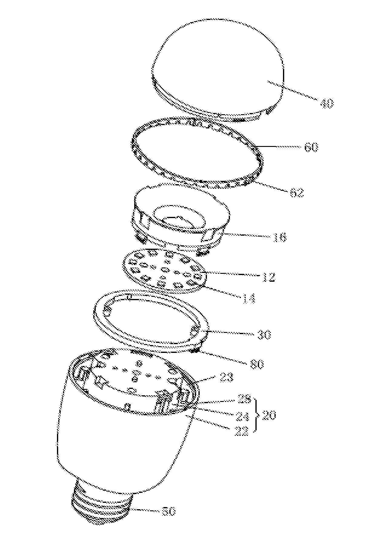
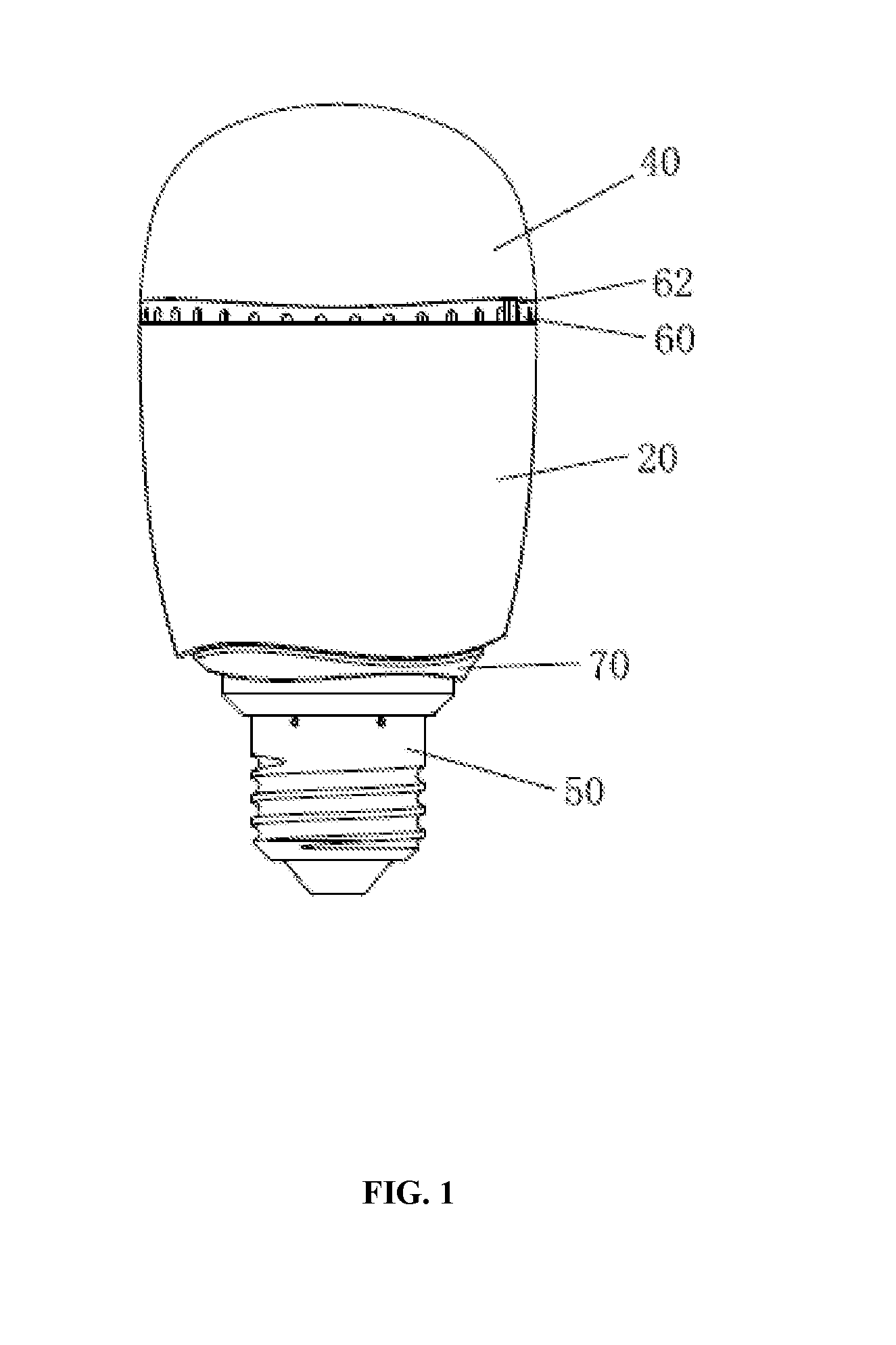
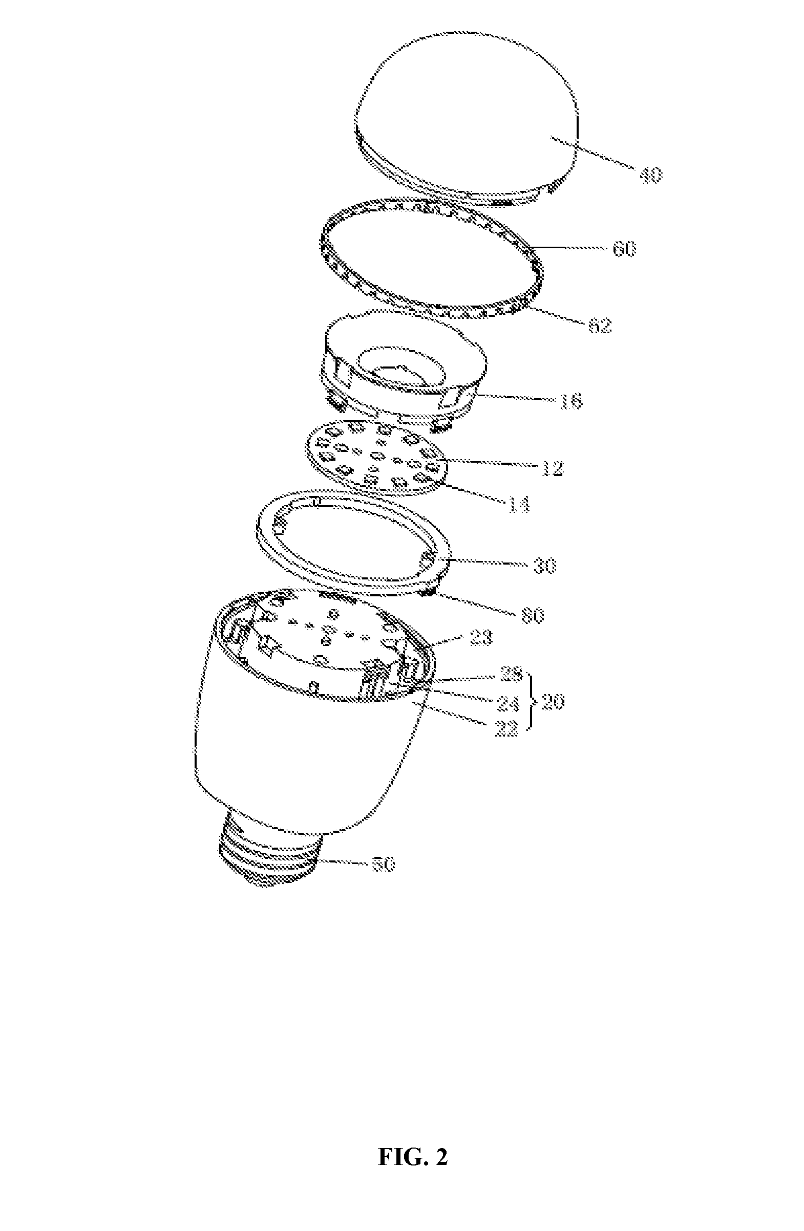
[0019]FIG. 1 illustrates a structure diagram of an exemplary LED lighting device consistent with the disclosed embodiments. FIG. 2 illustrates a blow-out diagram of an exemplary LED lighting device consistent with the disclosed embodiments. As shown in FIG. 1 and FIG. 2, the LED lighting device may include a lampshade 40, an LED driving and power supply unit, an LED light source assembly, a lamp shell 20, a control module, a wireless module, a RF antenna 30, a reset button 80, a enhancer 60, a plastic seat 70, and a lighting base 50. The lighting base 50 may be configured to electrically connect the LED lighting device to an external lighting holder. The plastic seat 70 is sleeved inside the lamp shell 20 and is located between th...


PUM


Abstract

A light emitting diode (LED) lighting device is provided. The device includes a lamp shell which is a heat sink including a heat sink covering and a heat sink body and an LED light source assembly installed on top of the heat sink body. The device also includes a control module configured to control the LED light source assembly and an LED driving and power supply unit configured to drive the LED light source assembly and provide electrical power for the LED lighting device. Further, the device includes a reset button electrically connected to the control module, wherein the reset button is set inside the lamp shell and a control push-button of the reset button is set at the sidewall of the lamp shell.

Description

CROSS-REFERENCES TO RELATED APPLICATIONS[0001]This PCT patent application is a national phase entry under 35 U.S.C. §371 of International Application No. PCT / CN2015 / 099054, filed on Dec. 25, 2015, which claims priority to Chinese Patent Application No. 201410833708.5, filed on Dec. 26, 2014, the entire contents of which are incorporated herein by reference.FIELD OF THE INVENTION[0002]The present disclosure generally relates to light emitting diode (LED) lighting technology and, more particularly, relates to LED lighting devices and systems, and related reset button arrangements.BACKGROUND[0003]Light emitting diode (LED) is a solid state semiconductor device that can convert electrical energy into visible light. The LED can directly convert electricity into light. LED lighting may generally provide advantages in energy conservation, environmental protection, controllable lighting, solid state lighting, and long operational lifetime. LED lamps thus have been widely used in various are...

Claims


Application Information

Patent Timeline
IPC IPC(8): F21V23/04H01L33/48F21V23/00F21V29/503F21K9/232F21K9/235H01L33/64F21V29/74
CPCF21V23/0435H01L33/644H01L33/486F21V23/04F21Y2115/10F21V29/503F21K9/232F21K9/235F21V23/004F21V29/74F21K9/23F21V17/00F21V23/0485F21Y2101/00H05B47/19F21V25/00F21V23/045F21Y2105/10F21V23/003F21K9/238
Inventor YOU, BOSHEN, JINXIANG
Owner SENGLED OPTOELECTRONICS
Why Eureka
Try Eureka