Heat dissipating system

a heat dissipating fan and heat dissipation technology, applied in the direction of instruments, modifications by conduction heat transfer, and semiconductor/solid-state device details, etc., can solve the problem of high temperature of electrical components, inability to easily customize the heat dissipating fan, and inability to heat dissipate fans. to achieve the effect of improving the problem

Active Publication Date: 2016-11-03
SU HSIENCHIN
View PDF3 Cites 9 Cited by
  • Summary
  • Abstract
  • Description
  • Claims
  • Application Information

AI Technical Summary

Benefits of technology

[0006]The instant disclosure provides a heat dissipating system for effectively improving the problem generated by the conventional heat dissipating fan.
[0008]In summary, the heat dissipating system of the instant disclosure is provided with a heat dissipating device which can be customized according to different heat generating members. Moreover, the sheet of each swing structure is formed of non-metal material and is installed with at least one buffering pad to prevent a stress concentration problem from occurring to each sheet, thus the useful life of the sheet of each swing structure is increased and stable.

Problems solved by technology

If heat cannot dissipate effectively, heat will cause the electronic component to have high temperature, which influences the operation of the electronic component.
For example, heat usually causes thermal shutdown of a heat generating member.
Moreover, the size of a conventional heat dissipating fan is unchanged, so the conventional heat dissipating fan cannot entirely align with each kind of heat generating member, thus part of the heat generating member is not arranged in a heat dissipating area defined by the conventional heat dissipating fan.
In other words, the heat dissipating fan is not easily customized.

Method used


Image

  • Heat dissipating system
  • Heat dissipating system
  • Heat dissipating system

Examples


first embodiment

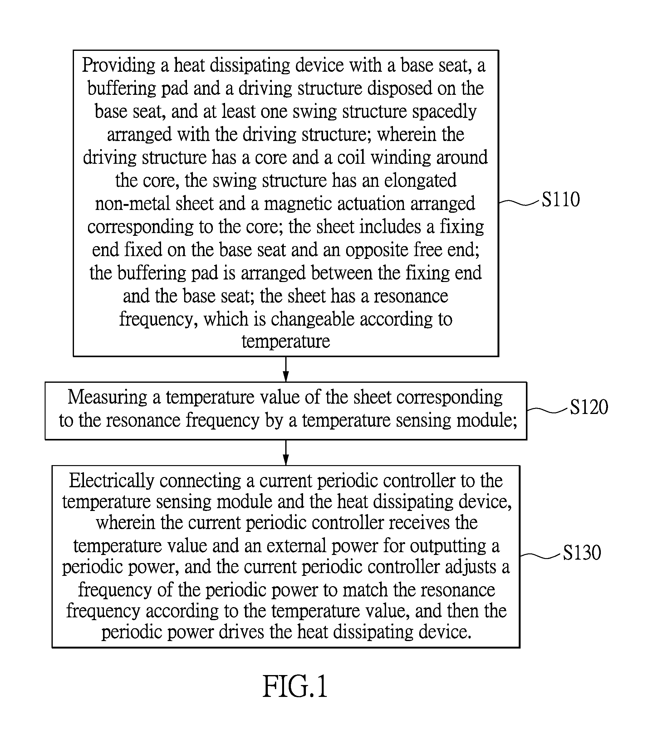
[0033]Please refer to FIGS. 1 through 6, which show the instant disclosure. References are hereunder made to the detailed descriptions and appended drawings in connection with the instant invention. However, the appended drawings are merely shown for exemplary purposes, rather than being used to restrict the scope of the instant invention.

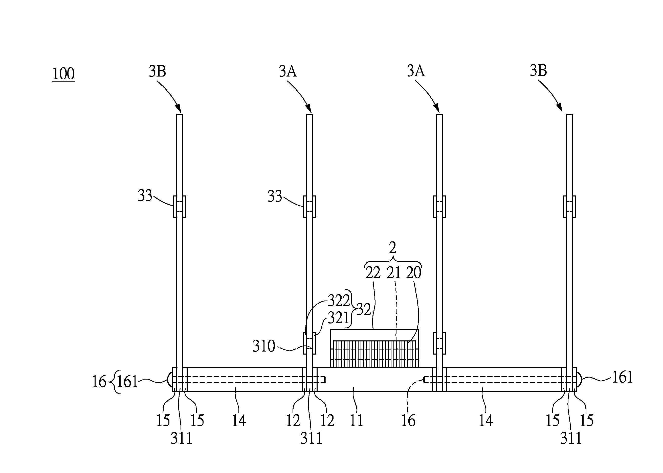
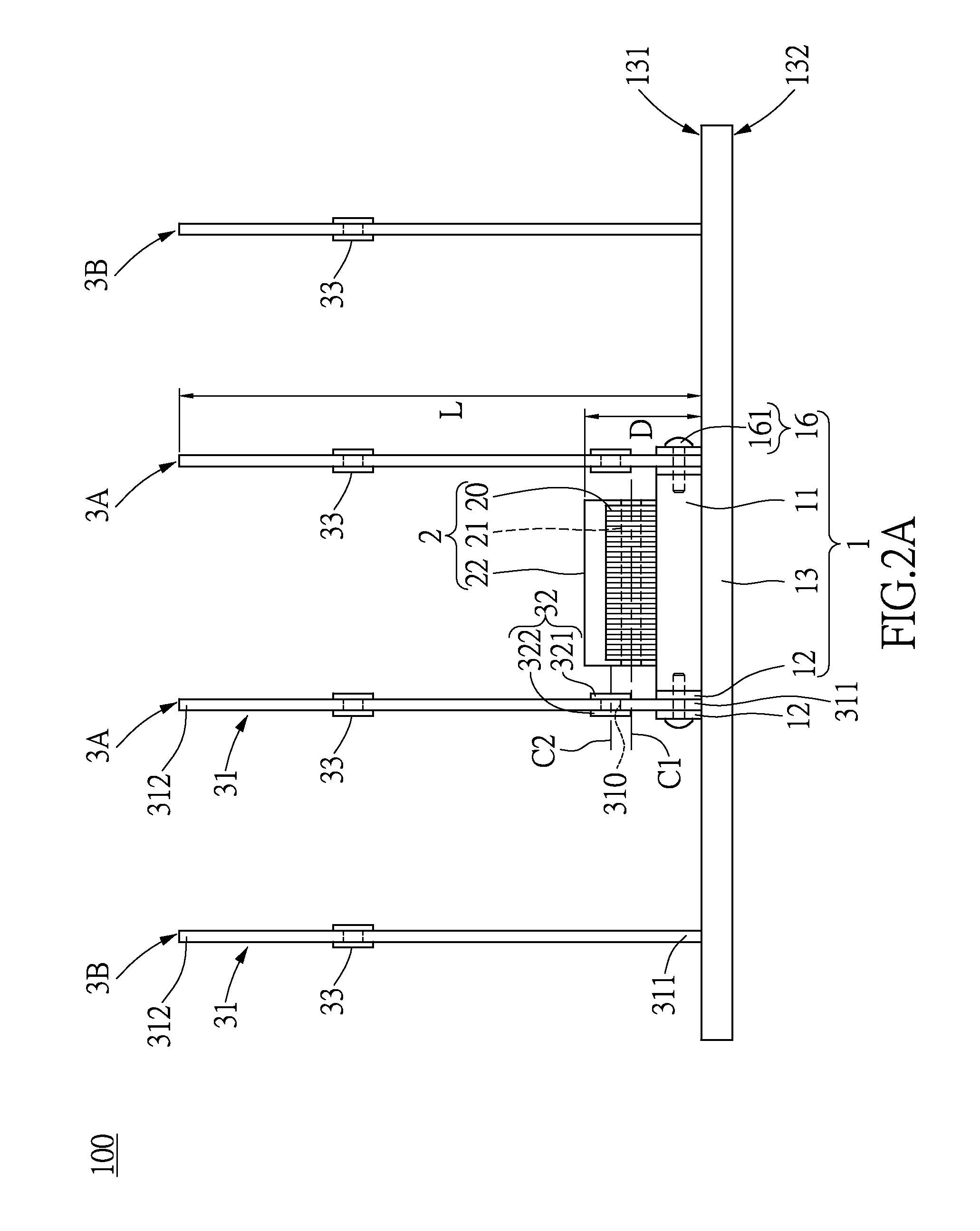
[0034]The instant disclosure provides a power frequency compensation method for a heat dissipating device 100, the heat dissipating device 100 has some specific requirements (e.g., heat dissipation by a swing structure) applied to the method. In order to clearly explain the power frequency compensation method, the following description firstly discloses the construction and operation of the heat dissipating device 100.

[0035]Please refer to FIG. 2A. The heat dissipating device 100 of the first embodiment of the instant disclosure is used for dissipating heat, which is generated from at least one heat generating member 9 (as shown in FIG. 4). The hea...

sixth embodiment

[0079]Please refer to FIG. 15, which shows a The instant embodiment provides a heat dissipating system 1000, which is based on the power frequency compensation method. In other words, the power frequency compensation method of the above description is implemented by operating the heat dissipating system 1000 of the instant embodiment. The heat dissipating system 1000 of the instant embodiment can be applied to a server host, tablet PC, desktop computer, or another system which needs the heat dissipation function, but is not limited thereto.

[0080]The heat dissipating system 1000 includes the heat dissipating device 100 as disclosed in the above embodiments, a current periodic controller 200, and a temperature sensing module 300. The specific construction of the heat dissipating device 100 has been disclosed in the above embodiments, so the construction of the heat dissipating device 100 is not disclosed again. The following description only discloses the relationship between the hea...


PUM


Abstract

A heat dissipating system comprises a heat dissipating device including a carrying structure, a driving structure, and at least one swing structure. The carrying structure has a base seat and at least one buffering pad disposed on the base seat. The driving structure is configured to be driven by a periodic power for generating a magnetic field, which has cyclical changes. The swing structure includes a non-metal sheet having an elongated shape and a magnetic actuation disposed on the sheet. The sheet has a fixing end and an opposite free end. The fixing end is fixed on the base seat, the base seat and the fixing end clips the buffering pad. When the magnetic actuation is driven by the magnetic field to repeatedly move forward and backward with respect to the driving structure, the sheet repeatedly swings by the movement of the magnetic actuation.

Description

BACKGROUND OF THE INVENTION[0001]1. Field of the Invention[0002]The instant invention relates to a heat dissipating system; in particular, to a heat dissipating system provided with a swing structure.[0003]2. Description of Related Art[0004]With the rapid development of electronic products, whether laptop, desktop, or tablet, etc., compared to the past, the effectiveness of the central processor and other electronic components had great improvement. However, if the volume of the electronic component is unchanged or decreased, the heat generated from an operating electronic component (e.g., heat generating member) will increase. If heat cannot dissipate effectively, heat will cause the electronic component to have high temperature, which influences the operation of the electronic component. For example, heat usually causes thermal shutdown of a heat generating member. The conventional solution is disposing a heat dissipating fan on a heat generating member, thereby reducing the tempe...

Claims


Application Information

Patent Timeline
Patent Type & Authority Applications(United States)
IPC IPC(8): G06F1/20H05K7/20
CPCH05K7/2039G06F1/20F04D33/00G06F1/206H01L23/3672H01L23/467
Inventor SU, HSIENCHIN
Owner SU HSIENCHIN
Why Eureka
Try Eureka