
Device for alignment of two substrates

Active Publication Date: 2016-11-03
EV GRP E THALLNER GMBH
View PDF1 Cites 0 Cited by
  • Summary
  • Abstract
  • Description
  • Claims
  • Application Information

AI Technical Summary

Benefits of technology

The technical effect of this patent is to improve the accuracy of aligning a device or method with a wafer surface, while also reducing scrap factors that result from alignment inaccuracies. Additionally, the invention aims to increase the speed of aligning multiple wafers.

Problems solved by technology

The system however works only based on the detected relative positions of the two alignment keys on both wafers to one another so that calibration of the microscopes to one another and the movement of the wafers in alignment can lead to errors in alignment.
Furthermore the number of measurement points on the wafer is limited.
In this connection the corresponding errors can occur by the relative motion of the wafers to one another and the relative detection of the alignment keys.
One major problem of the existing approaches is the mechanical accuracy of the movements of the components toward one another.
Another problem consists in the optical detection accuracy based on the required working distance of the optics from the wafers.
The necessity of this distance limits the maximum usable magnification of these microscopes and thus the maximum attainable detection accuracy for the alignment keys and subsequently the alignment accuracy.
In an arrangement of the optics between the wafers, the orthogonal alignment of the optics to the contact surfaces of the wafer is another aspect which leads to faults in the micron or nanometer range.

Method used


Image

  • Device for alignment of two substrates
  • Device for alignment of two substrates
  • Device for alignment of two substrates

Examples


Embodiment Construction

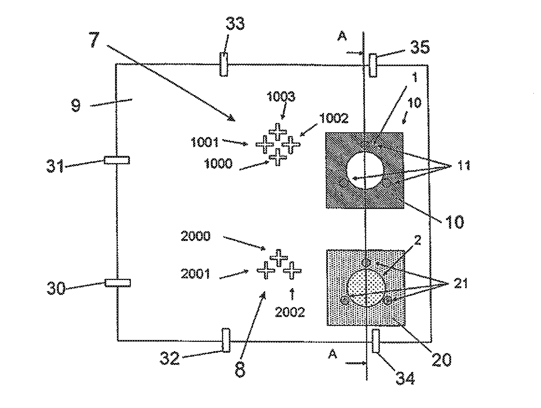
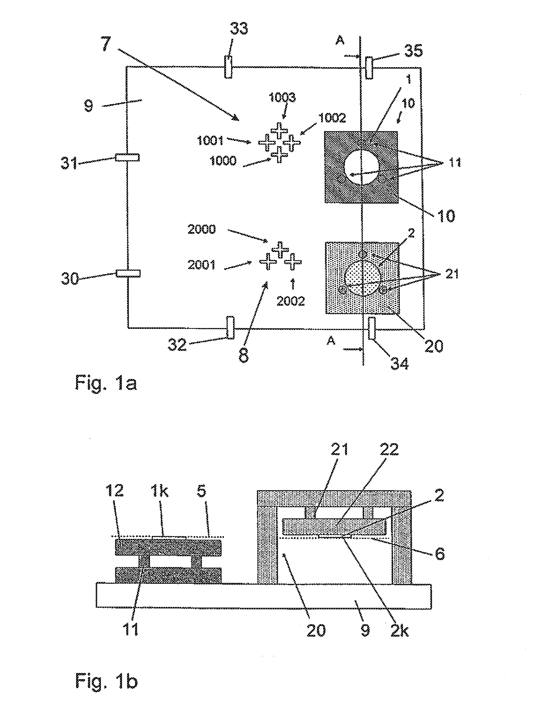
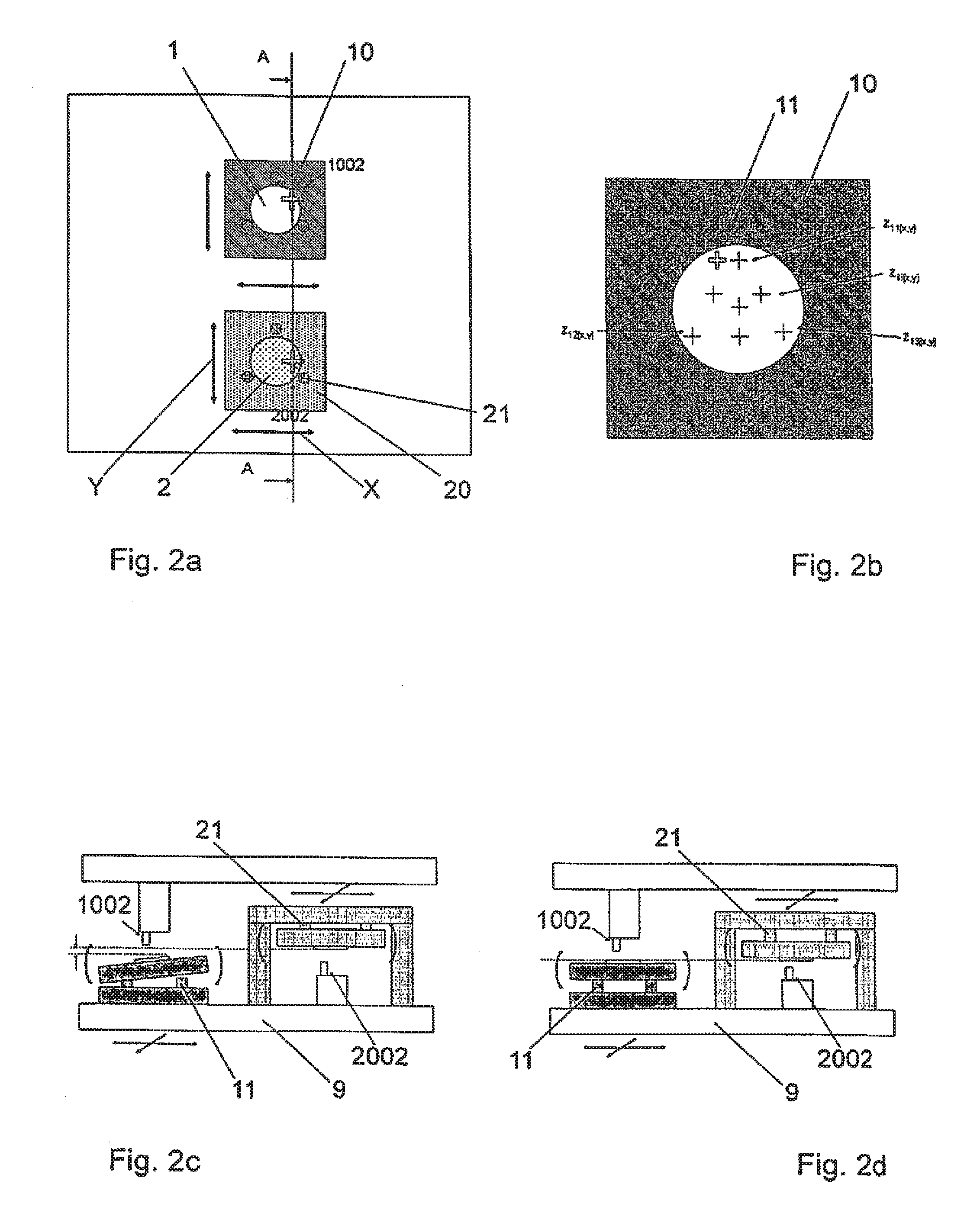
[0073]FIGS. 1a and 1b show a base 9 on which a first platform 10 and a second platform 20 are movably accommodated, especially by air supporting. The base 9 is advantageously formed from a stationary and / or solid and / or rigid material, especially granite. The movement of the first and second platform 10, 20, especially exclusively in the X and Y direction, can take place by drive means, especially linear motors which are located on the outer contour of the base 9. Each of the first and second platforms 10, 20 is assigned its own drive unit.

[0074]The drive unit is connected in a stable, nonflexible manner to the first or second platform 10, 20 assigned to it in order to transmit the drive forces without error and in a high precision manner to the first or second platform 10, 20. The drive units have a maximum deviation of <25 nm, especially <15 nm, preferably <5 nm.

[0075]A first substrate 1, especially a wafer, is held and fixed flat, especially by a vacuum, on the first platform 10....


PUM


Abstract

Device and method for alignment of a first contact surface of a first substrate with a second contact surface of a second substrate which can be held on a second platform. The device includes first X-Y positions of first alignment keys located along the first contact surface, and second X-Y positions of second alignment keys which correspond to the first alignment keys and which are located along the second contact surface, wherein the first contact surface can be aligned based on the first X-Y positions in the first alignment position and the second contact surface can be aligned based on the second X-Y positions in the second alignment position.

Description

RELATED APPLICATIONS[0001]The present application is a continuation of U.S. application Ser. No. 13 / 497,602, filed Mar. 22, 2012, which is a U.S. National Stage Application of International Application No. PCT / EP2010 / 005243, filed Aug. 26, 2010, which claims priority from European Patent Application No. 09012023.9, filed Sep. 22, 2009, said patent applications hereby fully incorporated herein by reference.FIELD OF THE INVENTION[0002]The invention relates to a device for alignment of the first contact surface of a first substrate with a second contact surface of a second substrate and a corresponding method.BACKGROUND OF THE INVENTION[0003]Various procedures are known for mutual arrangement and alignment of the contact surfaces of two substrates, for example wafers, especially nontransparent wafers.[0004]One known procedure is the use of two pairs of microscopes which are each calibrated to a certain viewing point. For purposes of alignment, first the lower wafer is moved to under th...

Claims


Application Information

Patent Timeline
IPC IPC(8): H01L21/68H01L21/67
CPCH01L21/67259H01L21/681H01L21/67092H01L21/02H01L21/68
Inventor FIGURA, DANIEL
Owner EV GRP E THALLNER GMBH
Learn More