Up-tower suspension system for a wind turbine rotor blade

Active Publication Date: 2016-11-10
GENERAL ELECTRIC CO
View PDF6 Cites 7 Cited by
  • Summary
  • Abstract
  • Description
  • Claims
  • Application Information

AI Technical Summary

Benefits of technology

This patent describes a way to attach cables to wind turbine blades using root attachment assemblies. The root attachment assembly is designed in a way that allows for easy removal and replacement of the attachment from the blade root. Bolt holes and barrel nut holes can be created in the blade to protect the cables when inserted through them. The technical effect of this patent is the improved durability and flexibility of the wind turbine blade cables.

Problems solved by technology

Such cranes are expensive and have to be transported to the wind turbine site, thereby accounting for much of the costs associated with up-tower maintenance and / or repairs of the wind turbine.

Method used


Image

  • Up-tower suspension system for a wind turbine rotor blade
  • Up-tower suspension system for a wind turbine rotor blade
  • Up-tower suspension system for a wind turbine rotor blade

Examples


Embodiment Construction

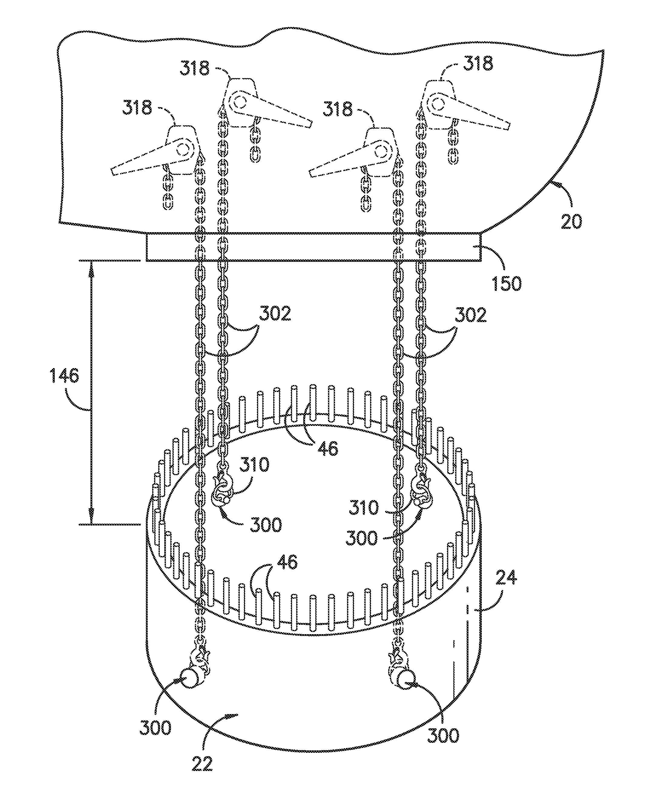
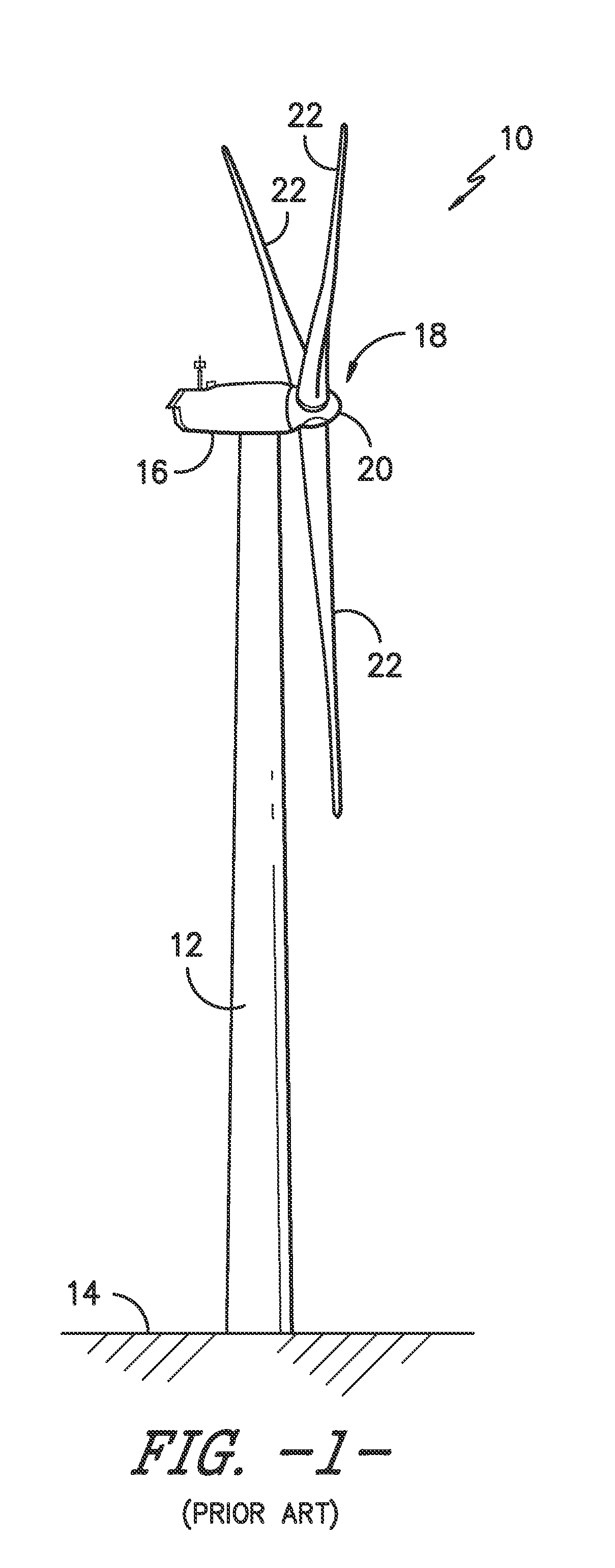
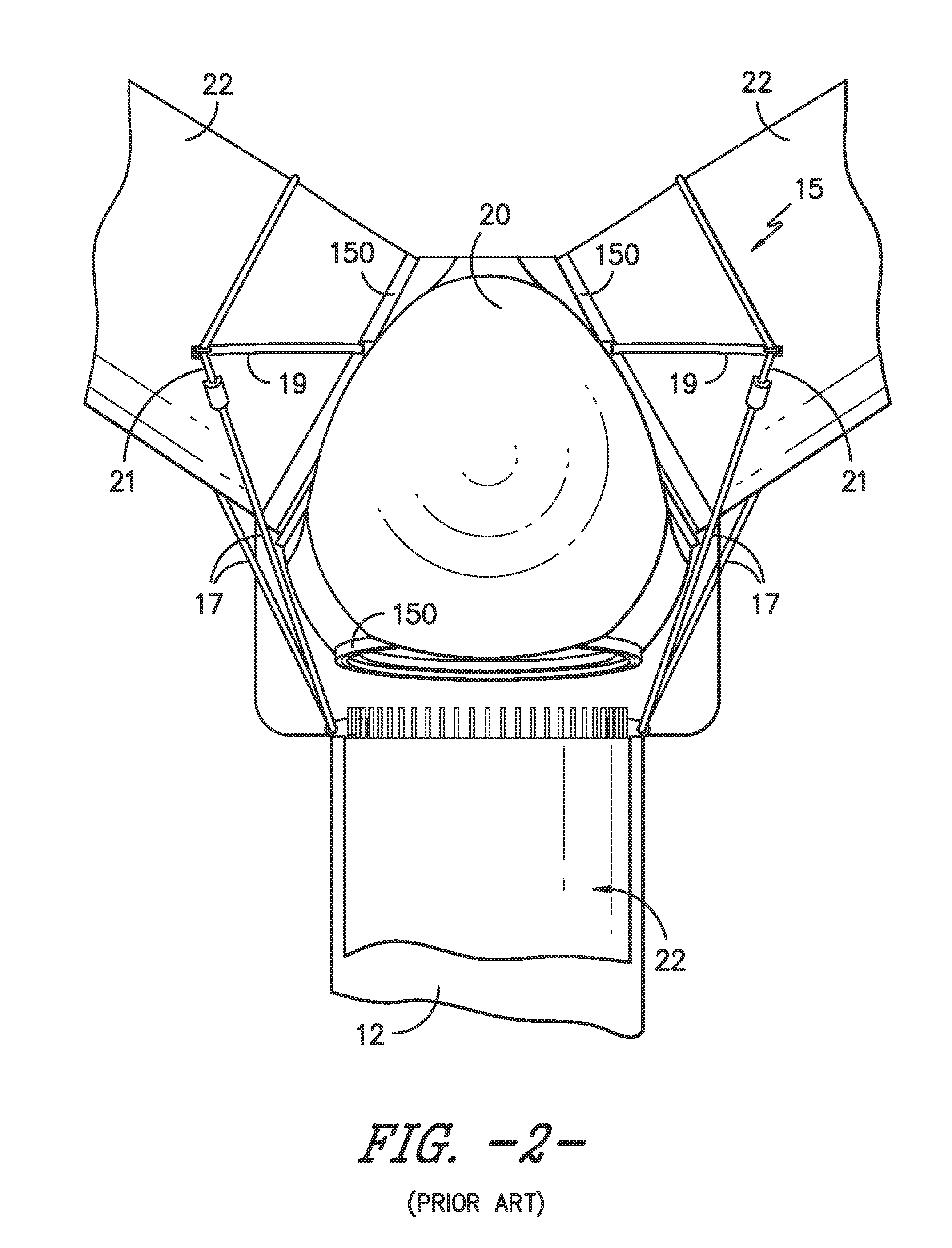
[0033]Reference now will be made in detail to embodiments of the invention, one or more examples of which are illustrated in the drawings. Each example is provided by way of explanation of the invention, not limitation of the invention. In fact, it will be apparent to those skilled in the art that various modifications and variations can be made in the present invention without departing from the scope or spirit of the invention. For instance, features illustrated or described as part of one embodiment can be used with another embodiment to yield a still further embodiment. Thus, it is intended that the present invention covers such modifications and variations as come within the scope of the appended claims and their equivalents.

[0034]Generally, the present subject matter is directed to various systems and methods for suspending a rotor blade of a wind turbine for completing service and / or maintenance work to various up-tower wind turbine components. Specifically, as will become ap...


PUM

PropertyMeasurementUnit
Lengthaaaaaaaaaa
Distanceaaaaaaaaaa
Distanceaaaaaaaaaa

Abstract

The present disclosure is directed to a suspension system for a wind turbine rotor blade and methods for suspending said rotor blade from a hub thereof. The method includes positioning the rotor blade in a substantially six o'clock position. Another step includes removing at least one root attachment assembly from an adjacent rotor blade and providing at least one passageway from an exterior surface of the adjacent rotor blade to the root attachment assembly. Still another step includes inserting a cable through the passageway such that the cable engages an interior surface of the adjacent rotor blade and extends from within the adjacent rotor blade to the lowered rotor blade. The method further includes securing the cable to the rotor blade at an attachment location. Next, the method includes lowering the rotor blade a vertical distance from the hub until the blade is supported by the cable.

Description

FIELD OF THE INVENTION[0001]The present disclosure relates generally to wind turbines, and more particularly to an up-tower suspension system for a wind turbine rotor blade.BACKGROUND OF THE INVENTION[0002]Wind power is considered one of the cleanest, most environmentally friendly energy sources presently available, and wind turbines have gained increased attention in this regard. As shown in FIG. 1, a modern wind turbine 10 typically includes a tower 12 extending from a support surface 14, a nacelle 16 mounted atop the tower 12, a generator and a gearbox (not shown) within the nacelle 16, and a rotor 18 mounted to the nacelle 16. The rotor 18 includes a rotatable hub 20 having one or more rotor blades 22 mounted thereto. Each of the rotor blades 22 are typically mounted to the hub via a pitch bearing. The pitch bearings are configured to change the pitch angle of each of the blades to capture kinetic energy of the wind using known airfoil principles. The rotor blades 22 transmit th...

Claims


Application Information

Patent Timeline
IPC IPC(8): F03D1/00B66D3/14F03D1/06
CPCF03D1/001F03D11/04B66D3/14F03D1/0675F03D1/0691F05B2240/916F03D13/10Y02E10/728F03D1/0658F05B2230/70Y10T29/4978Y10T29/49318Y10T29/4973Y10T29/49721Y02E10/72B23P6/002F03D13/20
Inventor NEUMANN, ULRICH WERNERPFEIFFER, GAYLON MITCHELLCOSTAIN, KEVINWILLMAN, STEPHANIE
Owner GENERAL ELECTRIC CO
Why Eureka
Try Eureka