
Methods And Systems For Specifying Metal Necking Failure Criteria In Finite Element Analysis

a finite element analysis and failure criteria technology, applied in the field of computer-aided engineering analysis, can solve problems such as simulation errors, and achieve the effect of avoiding obscuring the purpos

Active Publication Date: 2016-11-10
ANSYS
View PDF0 Cites 4 Cited by
  • Summary
  • Abstract
  • Description
  • Claims
  • Application Information

AI Technical Summary

Benefits of technology

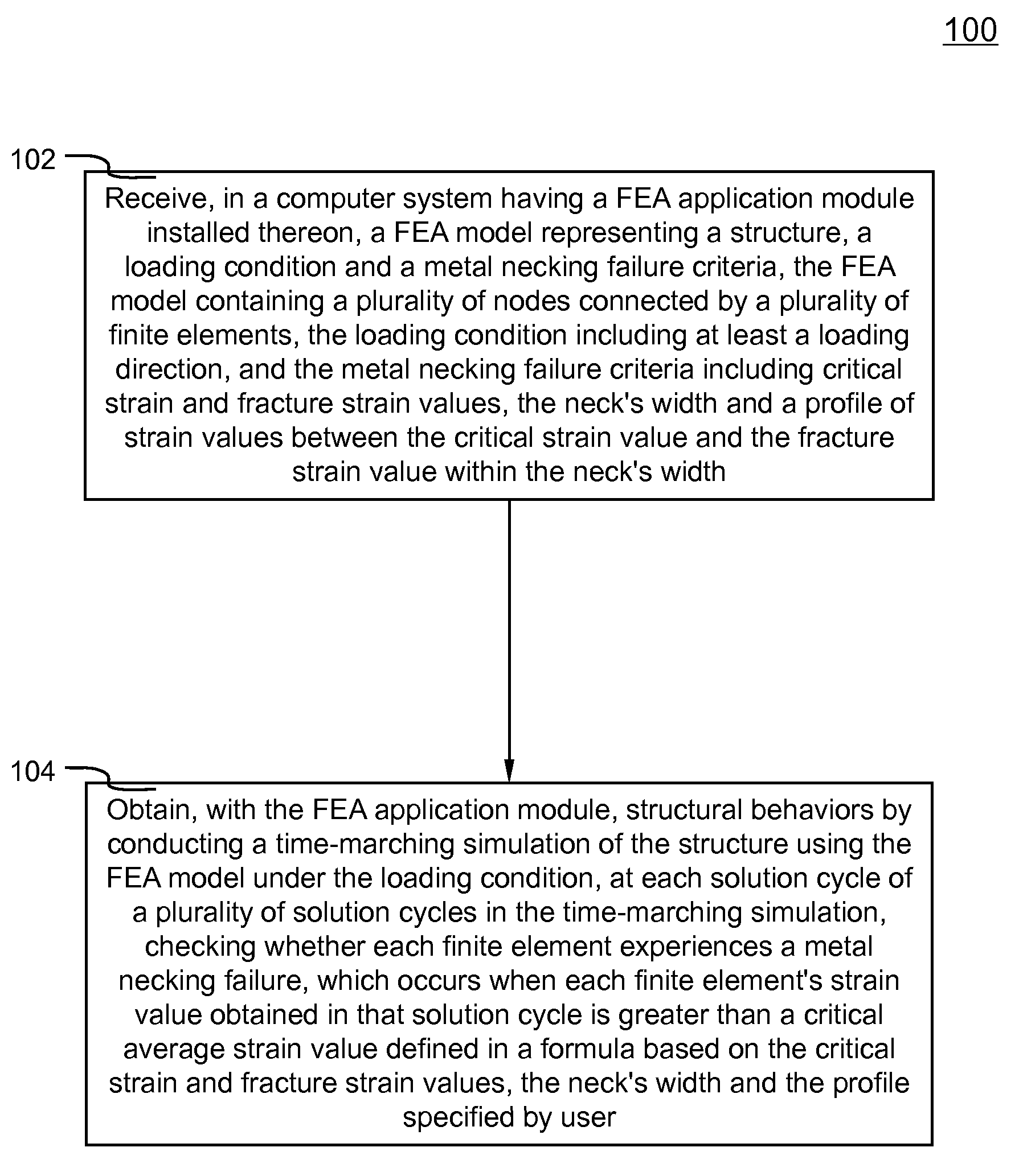
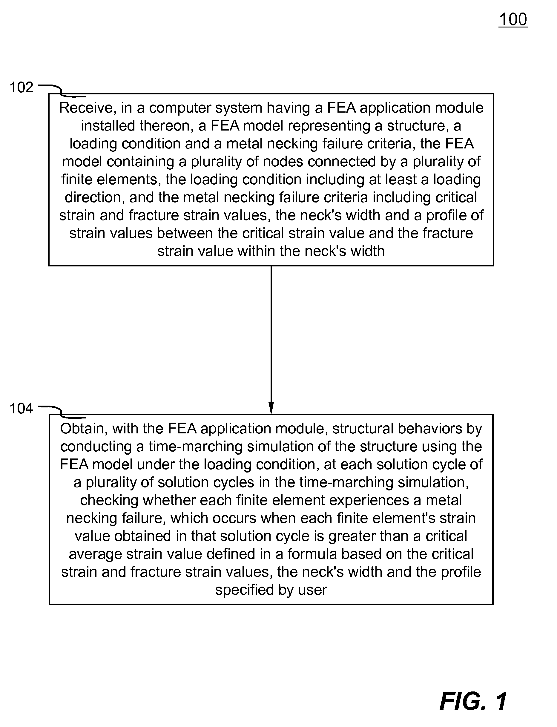
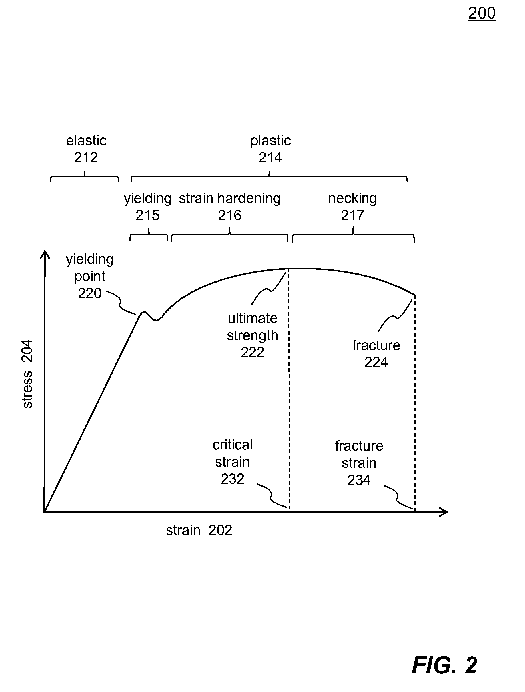
The present invention introduces a method and system for using finite element analysis (FEA) to evaluate the failure criteria of metal necking in a structure. A FEA model is created that includes a structure, a loading condition and metal necking failure criteria. The loading condition is the force applied to the structure in the direction of the metal necking failure. The metal necking failure criteria includes critical strain, fracture strain, the width of the metal neck, and a profile of strain values. The strain values are measured before the metal necking failure starts. Structural behaviors are obtained by conducting a time-marching simulation of the structure using the FEA model under the loading condition. Each finite element is checked to determine whether it experiences metal necking failure, which occurs if its strain exceeds the average strain value defined in a formula based on the critical strain, fracture strain, the width of the metal neck, and the profile of the metal necking failure criteria.

Problems solved by technology

These prior art approaches often cause confusions and difficulties for preparing input data and lead to incorrect simulation because users would need to prepare the failure criteria based on these artificial and ad hoc requirement.

Method used


Image

  • Methods And Systems For Specifying Metal Necking Failure Criteria In Finite Element Analysis
  • Methods And Systems For Specifying Metal Necking Failure Criteria In Finite Element Analysis
  • Methods And Systems For Specifying Metal Necking Failure Criteria In Finite Element Analysis

Examples


Embodiment Construction

[0018]In the following description, numerous specific details are set forth in order to provide a thorough understanding of the present invention. However, it will become obvious to those skilled in the art that the present invention may be practiced without these specific details. The descriptions and representations herein are the common means used by those experienced or skilled in the art to most effectively convey the substance of their work to others skilled in the art. In other instances, well-known methods, procedures and components have not been described in detail to avoid unnecessarily obscuring aspects of the present invention.

[0019]Reference herein to “one embodiment” or “an embodiment” means that a particular feature, structure, or characteristic described in connection with the embodiment can be included in at least one embodiment of the invention. The appearances of the phrase “in one embodiment” in various places in the specification are not necessarily all referrin...


PUM


Abstract

Methods and systems for specifying metal necking failure criteria in FEA are disclosed. FEA model contains many finite elements representing a structure, a loading condition and a metal necking failure criteria are received in a computer system. The loading condition includes a loading direction. The metal necking failure criteria includes critical strain and fracture strain values, the neck's width, and a profile of strain values between the critical strain value and the fracture strain value within the neck's width. At each solution cycle in the time-marching simulation of the structure, each finite element is check to determine whether it experiences a metal necking failure, which occurs when each finite element's strain obtained in that solution cycle is greater than an average strain value defined in a formula according to the critical strain and fracture strain values, the neck's width and the profile of the metal necking failure criteria.

Description

FIELD[0001]The present invention generally relates to computer-aided engineering analysis, more particularly to methods and systems for specifying metal necking failure criteria in finite element analysis.BACKGROUND[0002]Computer aided engineering (CAE) has been used for supporting engineers in many tasks. For example, in a structure or engineering product design procedure, CAE analysis, particularly finite element analysis (FEA), has often been employed to predict structural behavior (e.g., stresses, displacements, etc.) under various simulated loading conditions (e.g., static or dynamic).[0003]FEA is a computerized method widely used in industry to numerically simulate (i.e., model and solve in a computer system) engineering problems relating to complex products or systems (e.g., cars, airplanes, consumer products, etc.) such as three-dimensional non-linear structural design and analysis. FEA derives its name from the manner in which the geometry of the object under consideration ...

Claims


Application Information

Patent Timeline
IPC IPC(8): G06F17/50
CPCG06F17/5018G06F30/23G06F2113/24
Inventor ZHU, XINHAIHAN, ZHIDONG
Owner ANSYS
Learn More