Keyswitch structure

a keyswitch and key technology, applied in the direction of emergency actuators, contact mechanisms, electrical devices, etc., can solve the problems of affecting operation smoothness and comfortability, and achieve the effect of reducing operation nois

Active Publication Date: 2016-11-10
DARFON ELECTRONICS (SUZHOU) CO LTD +1
View PDF6 Cites 44 Cited by
  • Summary
  • Abstract
  • Description
  • Claims
  • Application Information

AI Technical Summary

Benefits of technology

[0006]In view of the prior arts, it is an object of the invention to provide a keyswitch structure to effectively reduce the operation noise.

Problems solved by technology

When the user presses the keycap, the engaging portion protruding from the keycap will hit the baseplate and generate loud noise, impairing the operation smoothness and comfortability.

Method used


Image

  • Keyswitch structure
  • Keyswitch structure
  • Keyswitch structure

Examples


Embodiment Construction

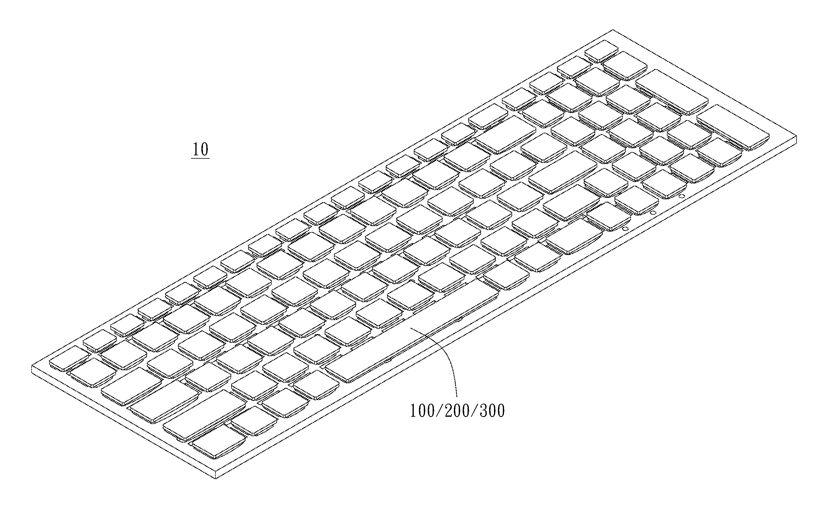
[0032]The invention provides a keyswitch structure of low noise design and a keyboard having the keyswitch structure. Particularly, the keyswitch structure of the invention can be a keyswitch of the computer keyboard, but not limited thereto. The keyswitch structure of the invention can be a button, a numeral key, etc. of other electronic devices. The keyswitch structure of the invention can be any suitable keyswitch structure having an engaging portion, particularly a keyswitch structure having the engaging portion connected to the linking bar, such as larger-sized key of the keyboard, but not limited thereto. Hereafter, a computer keyboard is illustrated as an example to explain the details of the keyswitch structure of the invention.

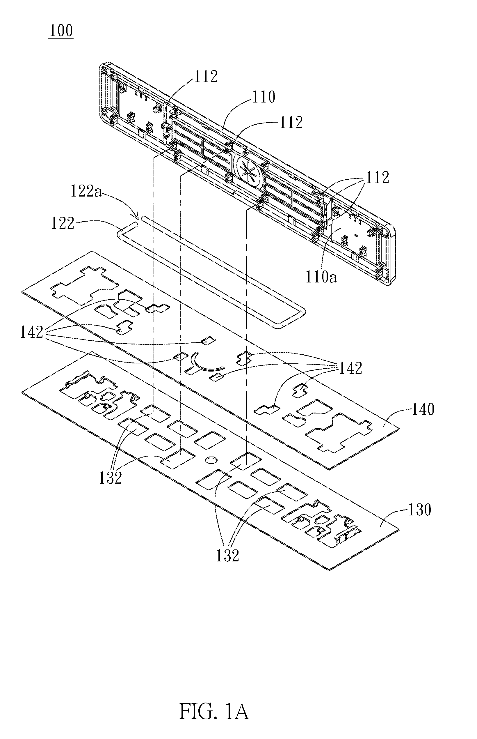
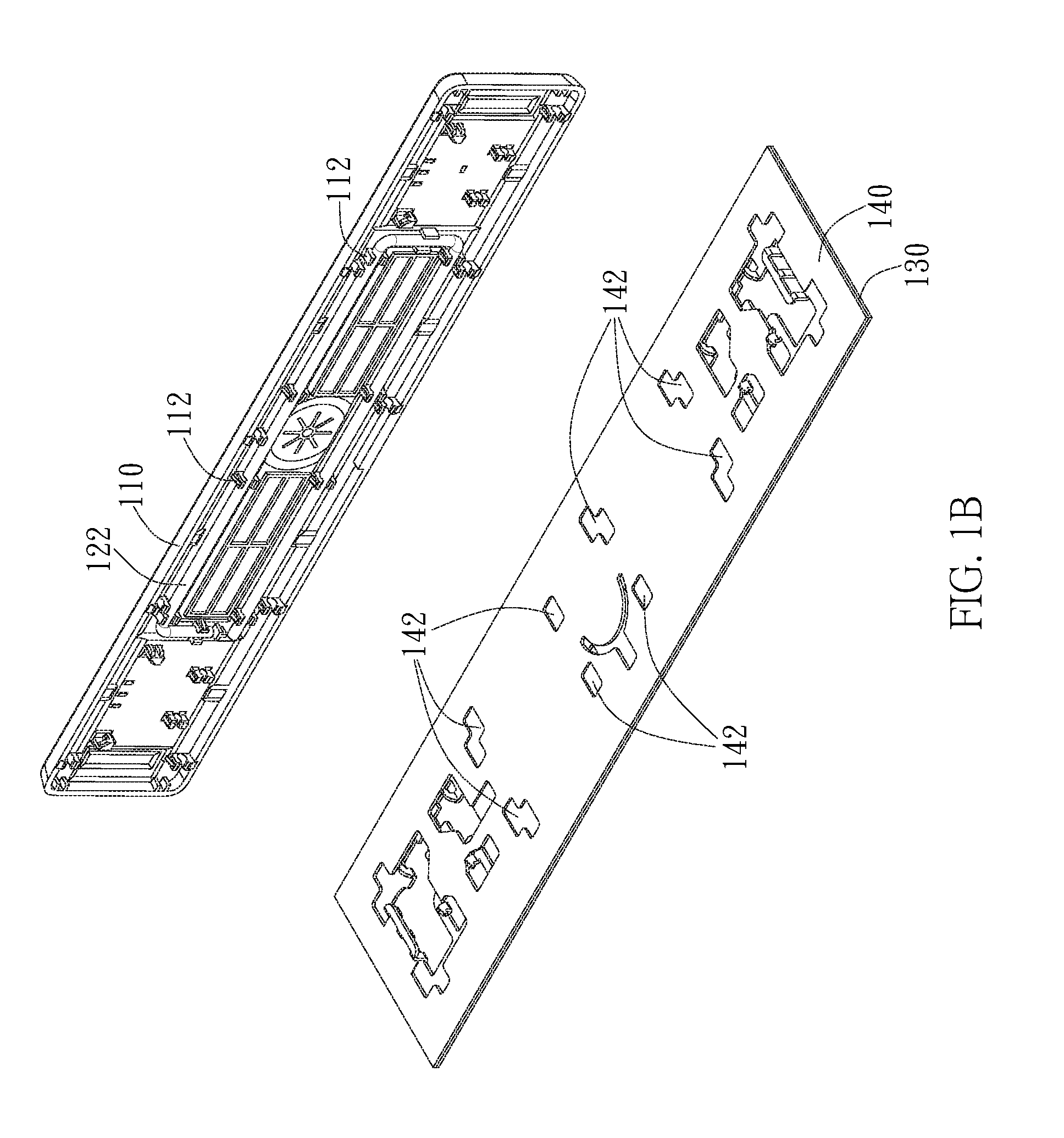
[0033]As shown in FIGS. 1A and 6A, in an embodiment, the keyswitch structure 100 / 200 of the invention includes a keycap 110, a linking bar 122 / 124, a baseplate 130, and a buffer film 140. The keycap 110 is disposed over the baseplate 130 and is downwa...


PUM


Abstract

A keyswitch structure includes a keycap having a lower surface and an engaging portion protruding from the lower surface, the keycap moving to a lower position when the keycap is pressed, a linking bar coupled with the engaging portion, a distal end of the engaging portion being lower than the linking bar when the keycap moves to the lower position, a baseplate disposed below the keycap, the baseplate having a recessed space corresponding to the engaging portion, and a buffer film disposed on the baseplate, the buffer film substantially extending over the recessed space and having a deformable portion corresponding to the recessed space, wherein when the keycap moves toward the baseplate to the lower position, the distal end of the engaging portion pushes the deformable portion to make the deformable portion extend into the recessed space.

Description

BACKGROUND OF THE INVENTION[0001]1. Field of the Invention[0002]The invention generally relates to a keyswitch structure. Particularly, the invention relates to a keyswitch structure of low noise design.[0003]2. Description of the Prior Art[0004]Keyboard devices generally have regular-sized keys and larger-sized keys, such as Space key, Enter key, Caps Lock key, Shift key. The larger-sized keys usually have one or more linking bars to enhance the strength of the keycap. Moreover, by means of the linking bar, when the user presses the keycap on the non-center portion, the larger-sized key is prevented from slanting during the pressing operation. The linking bar is generally connected to the engaging portion that protrudes from the lower surface of the keycap. When the user presses the keycap, the engaging portion protruding from the keycap will hit the baseplate and generate loud noise, impairing the operation smoothness and comfortability.[0005]Therefore, how to effectively reduce t...

Claims


Application Information

Patent Timeline
Patent Type & Authority Applications(United States)
IPC IPC(8): H01H3/12H01H13/705H01H13/52
CPCH01H3/122H01H13/705H01H13/52H01H3/125H01H2009/0278H01H2217/004H01H2217/016H01H2221/062
Inventor HOU, PO-CHUNGYANG, SUNG-FU
Owner DARFON ELECTRONICS (SUZHOU) CO LTD
Why Eureka
Try Eureka