Method and Control Apparatus for Controlling a High-Pressure Fuel Supply Pump

a fuel supply pump and control apparatus technology, applied in the direction of electric control, charge feed system, machines/engines, etc., can solve the problem of dominant operation noise and achieve the effect of reducing operating nois

Inactive Publication Date: 2012-01-05
HITACHI LTD
View PDF19 Cites 29 Cited by
  • Summary
  • Abstract
  • Description
  • Claims
  • Application Information

AI Technical Summary

Benefits of technology

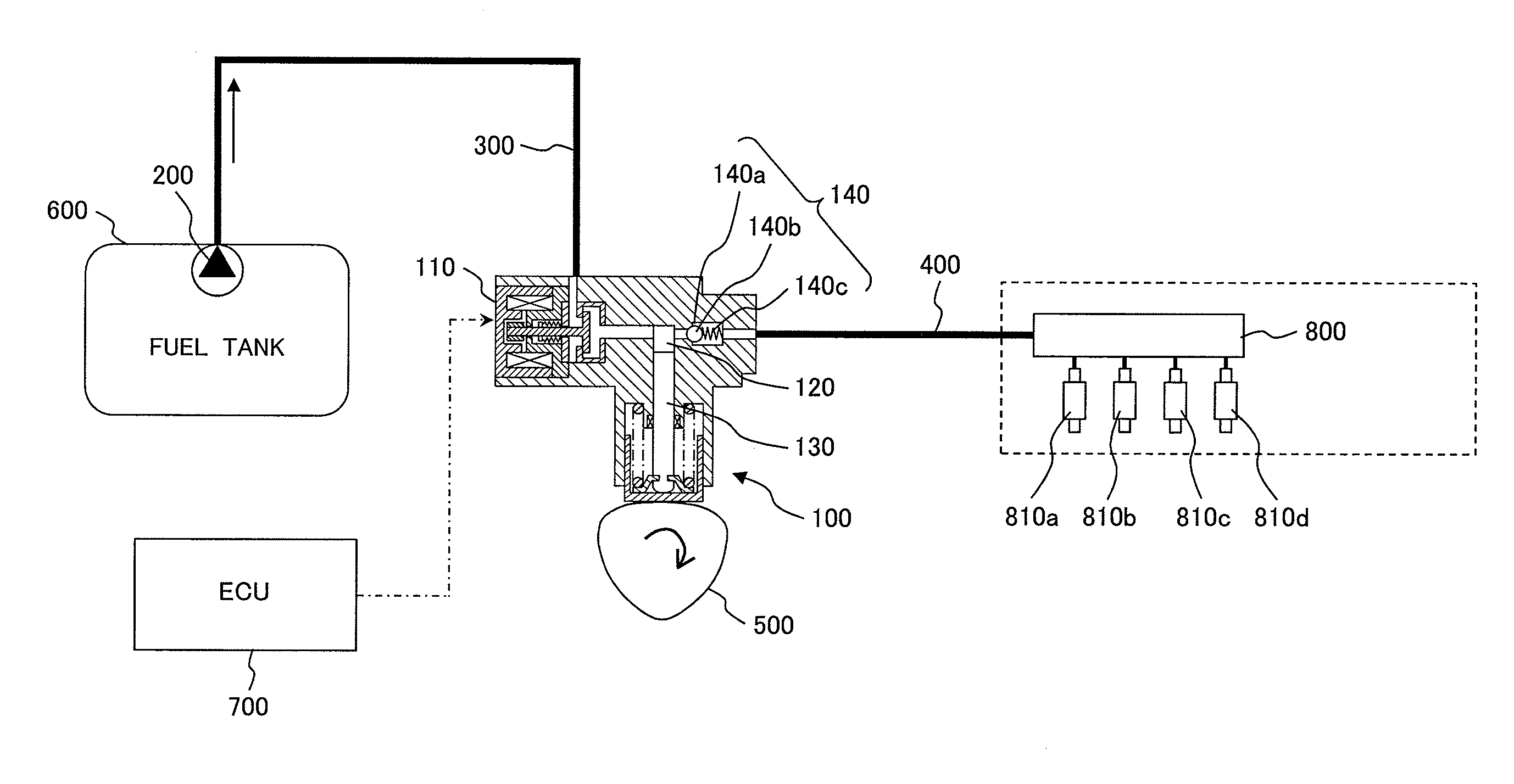
[0011]It is an object of the present invention to reduce the operating noise of a high-pressure fuel supply pump that is configured to supply pressurized fuel to an internal combustion engine and comprises a normally-closed type solenoid actuated intake valve which is configured to be opened or kept open by magnetic force.

Problems solved by technology

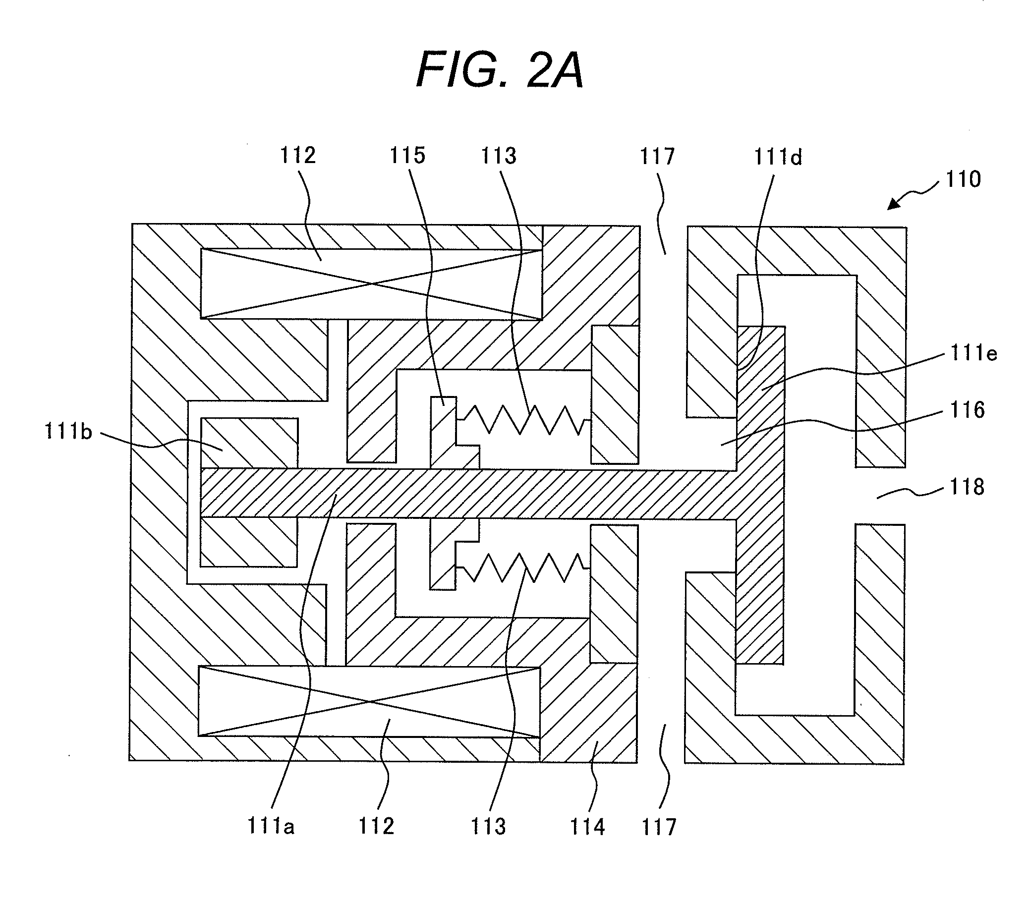
However, in such high-pressure fuel supply systems, especially in low-rotational speed conditions of the motor such as for example during an idle operation of the internal combustion engine, the dominant operation noise is the noise emitted from the solenoid actuated intake valve, in particular, the noise generated when closing and opening the valve, e.g. when an intake valve member of the solenoid actuated intake valve comes in contact with a valve seat in the fully closed position of the valve.

Method used


Image

  • Method and Control Apparatus for Controlling a High-Pressure Fuel Supply Pump
  • Method and Control Apparatus for Controlling a High-Pressure Fuel Supply Pump
  • Method and Control Apparatus for Controlling a High-Pressure Fuel Supply Pump

Examples


first embodiment

[0120]FIG. 7 shows the control of the control current IC of the solenoid actuated intake valve 110 according to a method for controlling a high-pressure fuel supply pump according to a first embodiment of the present invention. The upper row shows a PWM control voltage signal VC for controlling the control current IC according to the lower row in FIG. 7.

[0121]At a first point in time t1, before the movable compression plunger 130 reaches the bottom dead center position BDC and until a time t2 (with t2−t1=ΔT1), an initial voltage signal IVP is supplied to the coil 112 of the solenoid actuated intake valve 110 (e.g. a PWM voltage signal having 100% duty cycle) for increasing the control current IC to a control current value IC1 for energizing the solenoid actuated intake valve 110 for opening the valve. Starting from time t2, a PWM voltage signal VCF is applied to coil 112 of the solenoid actuated intake valve 110 having a duty cycle smaller than 100%, in particular a duty cycle that ...

second embodiment

[0125]FIG. 9 shows the control of the control current IC of the solenoid actuated intake valve 110 according to a method for controlling a high-pressure fuel supply pump according to a second embodiment of the present invention. The upper row shows a PWM control voltage signal VC for controlling the control current IC according to the lower row in FIG. 9.

[0126]Similar to the first embodiment, at time t1 until time t2, an initial voltage pulse IVP is supplied for increasing the control current IC in the coil 112 up to a control current value IC1. Starting from time t2, a PWM voltage control signal VC1 is applied for decreasing the control current IC to the control current value IC2, similar to the first embodiment. This has the effect, that the movement of the intake valve member 111e towards the fully open position is decelerated after time t2 or at least the acceleration thereof is reduced.

[0127]For achieving an optimal deceleration of the movement of the intake valve member 111e t...

third embodiment

[0134]FIG. 11 shows the control of the control current IC of the solenoid actuated intake valve 110 according to a method for controlling a high-pressure fuel supply pump according to a third embodiment of the present invention. The upper row shows a PWM control voltage signal VC for controlling the control current IC according to the lower row in FIG. 11.

[0135]According to the third embodiment as illustrated with reference to FIG. 11, the increase from the current control value IC2 to the final target control current value IT for keeping the intake valve fully opened after the compression plunger 130 has reached the bottom dead center position, the control current IC is only gradually increased in order to ensure a soft landing at the fully-opened position even in case of mass production deviations described with reference to the second embodiment above.

[0136]According to the third embodiment, as illustrated in the upper row of FIG. 11, a plurality of PWM voltage control signals VC...


PUM


Abstract

The present invention relates to a control apparatus 700 for controlling a high-pressure fuel supply pump 100, a computer program product comprising computer program code means configured to adapt a control apparatus 700 for controlling a high-pressure fuel supply pump 100, and a method for controlling a high-pressure fuel supply pump 100 configured to supply pressurized fuel to an internal combustion engine. The high-pressure fuel supply pump 100 comprises a normally-closed type solenoid actuated intake valve 110 configured to be opened or kept open by magnetic force. A control current IC of the solenoid actuated intake valve 110 is controlled for opening the solenoid actuated intake valve 110 by applying a control voltage VC to the solenoid actuated intake valve 110. Controlling a control current IC of the solenoid actuated intake valve 110 comprises increasing the control current IC to a first control current value IC1 for energizing the solenoid actuated intake valve 110. Controlling a control current IC of the solenoid actuated intake valve 110 for opening the solenoid actuated intake valve 110 according to the present invention further comprises reducing the control current IC from the first control current value IC1 to a second control current value IC2 being smaller than the first control current value IC1.

Description

CLAIM OF PRIORITY[0001]The present application claims priority from European Patent Application No. P10168022.1 filed on Jun. 30, 2010 and No. P10172572.9 filed on Aug. 11, 2010, the content of which are hereby incorporated by reference into this application.BACKGROUND OF THE INVENTION[0002]1. Field of the Invention[0003]The present invention relates to a method for controlling a high-pressure fuel supply pump that is configured to supply pressurized fuel to an internal combustion engine and to a control apparatus for controlling such a high-pressure fuel supply pump. Furthermore, the present invention relates to a computer program product comprising computer program code means configured to adapt a control apparatus, in particular an engine control unit, such that the control apparatus is adapted to control the high-pressure fuel supply pump.[0004]The present invention specifically relates to a method and a control apparatus for controlling a high-pressure fuel supply pump comprisi...

Claims


Application Information

Patent Timeline
Patent Type & Authority Applications(United States)
IPC IPC(8): F02M37/06F02D41/26
CPCF02D41/20F02D2041/2027F02D41/3854F02D41/3845
Inventor BORG, JONATHANWATANABE, MASANORITOKUO, KENICHIRO
Owner HITACHI LTD
Why Eureka
Try Eureka