

Pneumatic tire
Active Publication Date: 2016-11-17
SUMITOMO RUBBER IND LTD
View PDF4 Cites 6 Cited by
- Summary
- Abstract
- Description
- Claims
- Application Information
AI Technical Summary
Benefits of technology
[0003]It is therefore, an object of the present invention to provide a pneumatic tire in whic
Problems solved by technology
Such arrangement of the shallow groove sections and deep groove sections has a tendency that the ri
Method used
View moreImage
Smart ImageViewing Examples

Examples
 PUM
 Abstract
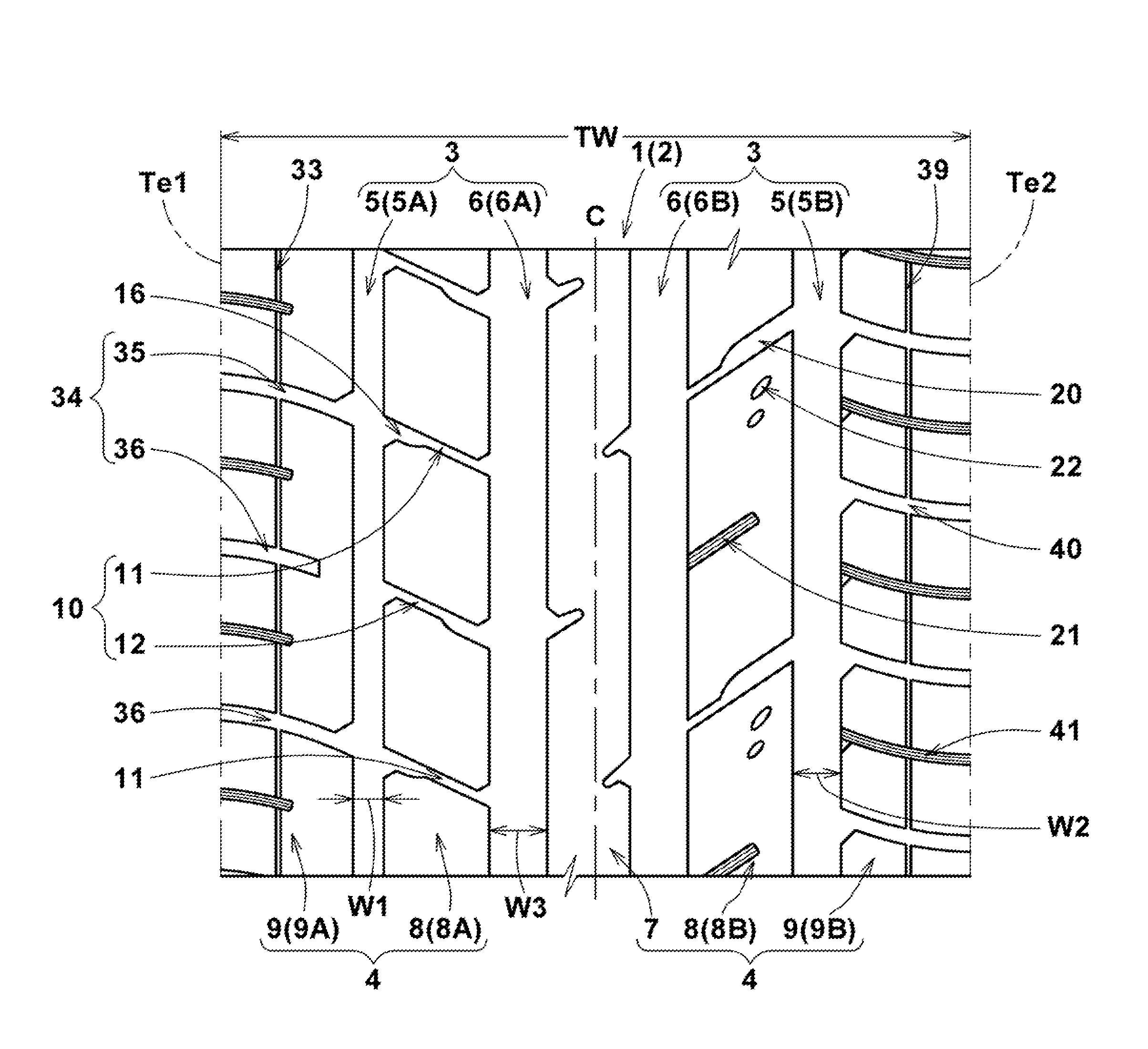
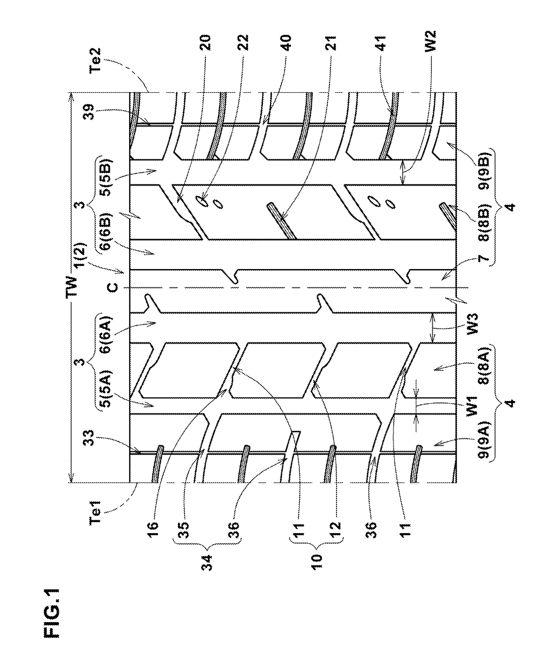
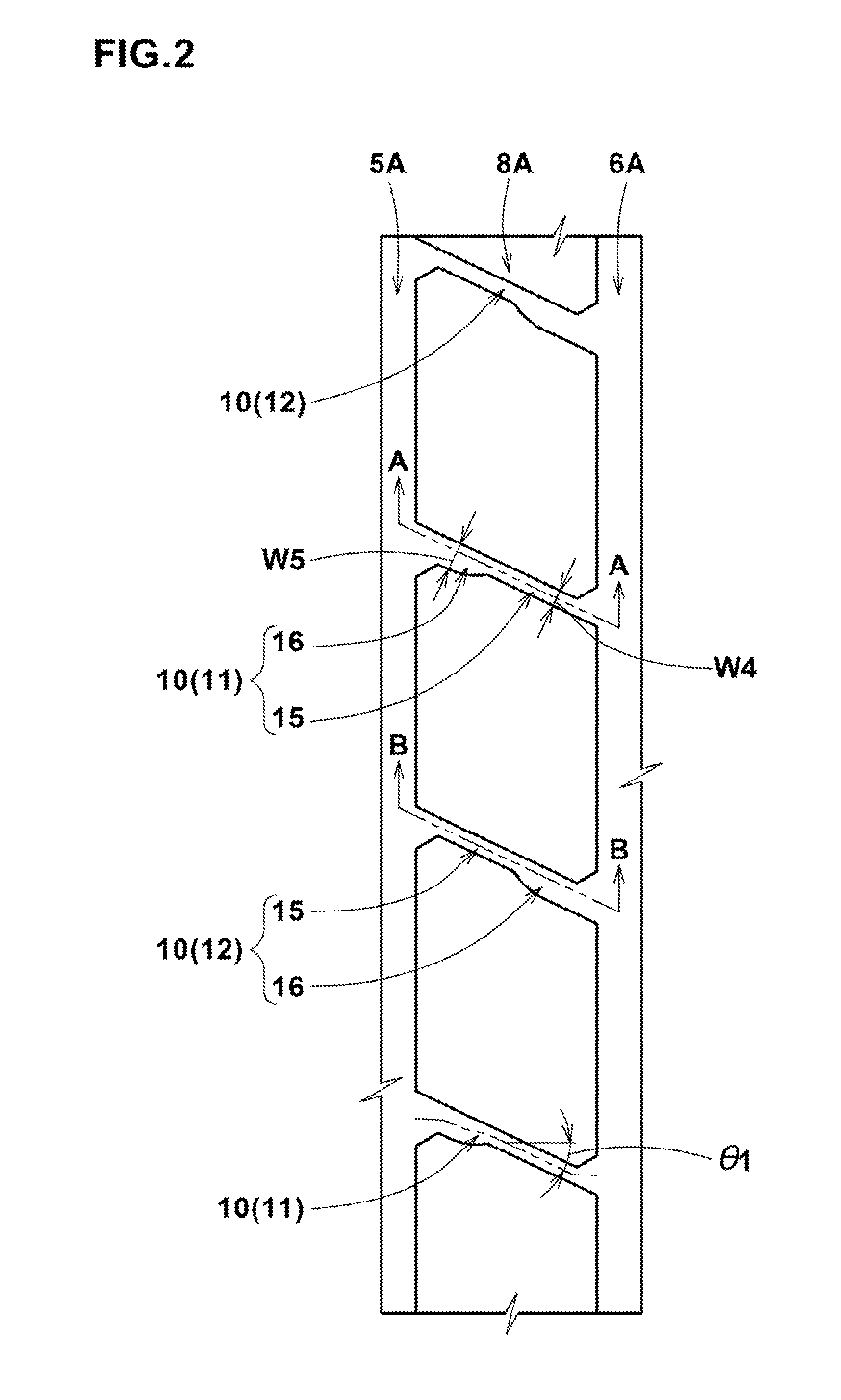
A pneumatic tire comprises a tread portion provided with main grooves extending continuously in the tire circumferential direction. The main grooves include an outboard shoulder main groove and an outboard crown main groove between which an outboard middle land region is defined. The outboard middle land region is provided with outboard middle transverse grooves each comprising a shallow groove section and a deep groove section. The outboard middle transverse grooves include: first outboard middle transverse grooves wherein their deep groove sections are is disposed on the outboard shoulder main groove side and their shallow groove sections are disposed on the outboard crown main groove side; and second outboard middle transverse grooves wherein their deep groove sections are disposed on the outboard crown main groove side and their shallow groove sections are disposed on the outboard shoulder main groove side. The first and second outboard middle transverse grooves arranged alternately in the tire circumferential direction.
Description
BACKGROUND OF THE INVENTION[0001]The present invention relates to a pneumatic tire, more particularly to a tread pattern capable of improving steering stability on dry roads while maintaining wet performance.[0002]In Japanese Patent Application Publication No. 2013-177114, a pneumatic tire is disclosed, wherein the tread portion is provided in an outboard middle land region with transverse grooves having a shallow groove section and a deep groove section. All of the shallow groove sections of the transverse grooves are disposed on the tire equator side, and accordingly, all of the deep groove sections are disposed on the outboard tread edge side. Such arrangement of the shallow groove sections and deep groove sections has a tendency that the rigidity of the outboard middle land region is excessively decreased on the outboard tread edge side. Therefore, the pneumatic tire disclosed in the above-mentioned patent document has a room for improvement in the steering stability on dry road...
Claims
Login to View More Application Information
Patent Timeline
 IPC IPC(8): B60C11/03B60C11/13
CPCB60C11/0332B60C11/0304B60C11/1353B60C2011/0334B60C2011/0341B60C2011/0369B60C2011/0365B60C11/0302B60C11/03B60C11/1259B60C11/1392B60C2011/0362B60C11/0306B60C11/032B60C2011/0372
InventorSANAE, RYUHEI
OwnerSUMITOMO RUBBER IND LTD