
Automatically adjust sensor sample rates and modes based on sensor feedback and system state

a sensor and system state technology, applied in the field of automatic adjustment of sensor sample rate and mode based on sensor feedback and system state, can solve the problems of large amount of power consumption, path light may not respond optimally to the detected user presence and ambient light conditions, and achieve the effect of accurate measurement of ambient ligh

Active Publication Date: 2016-11-24
GOOGLE LLC
View PDF9 Cites 19 Cited by
  • Summary
  • Abstract
  • Description
  • Claims
  • Application Information

AI Technical Summary

Benefits of technology

The patent describes a system and method for automatically controlling the lighting on a path using multiple sensors and sampling modes. The system analyzes data from sensors like ambient light levels, occupancy detection, and sensor position and movement to determine the best time to switch between sampling modes and periods. This allows the system to accurately measure ambient light without excessive operation, while also avoiding sensor operation when the device is not moving or the data is not applicable. The system can control the lighting on the path to user comfort and energy efficiency.

Problems solved by technology

However, since many of the path light control devices are battery powered, each has to consider how frequently power is used to sample the associated environmental sensors, such as ambient light sensors (ALS), which can consume large amounts of power.
At the same time, the control device needs to react quickly to various events such as a moving presence in the path light environment or the switching on and off of other light sources in the area, so it cannot sample the sensors too infrequently.
Accordingly, in some situations, the path light may not respond in an optimal manner to the detected user presence and ambient light conditions.
For example, the path light may operate using a single sampling mode or sampling period which can be inefficient when conditions indicate another sampling mode or sampling period may perform better.
In cases where the path light can operate using multiple sampling modes or sampling periods, the transition between each may not be designed to balance user comfort, energy efficiency, sensor position and proper system function.

Method used


Image

  • Automatically adjust sensor sample rates and modes based on sensor feedback and system state
  • Automatically adjust sensor sample rates and modes based on sensor feedback and system state
  • Automatically adjust sensor sample rates and modes based on sensor feedback and system state

Examples


Embodiment Construction

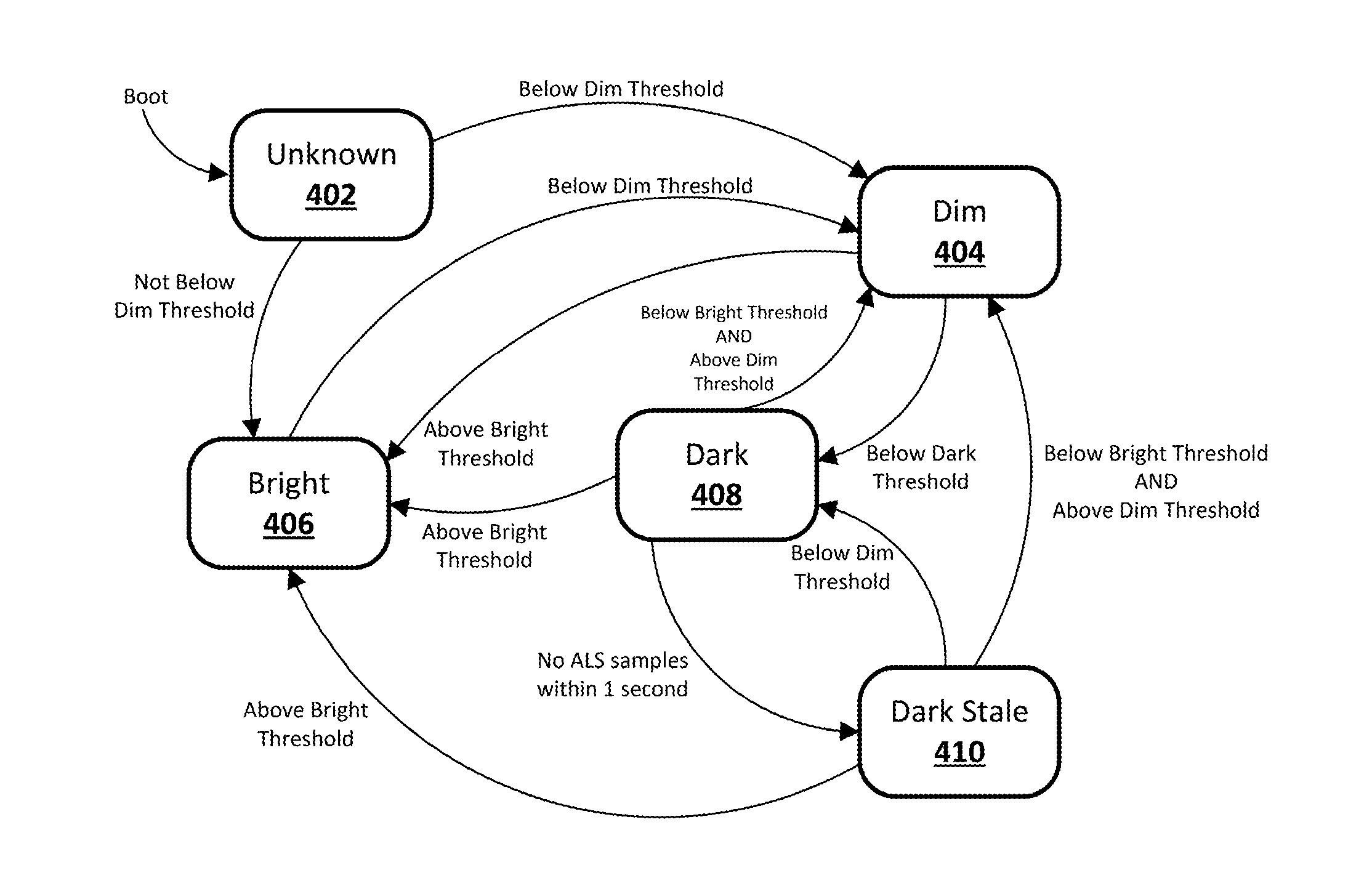
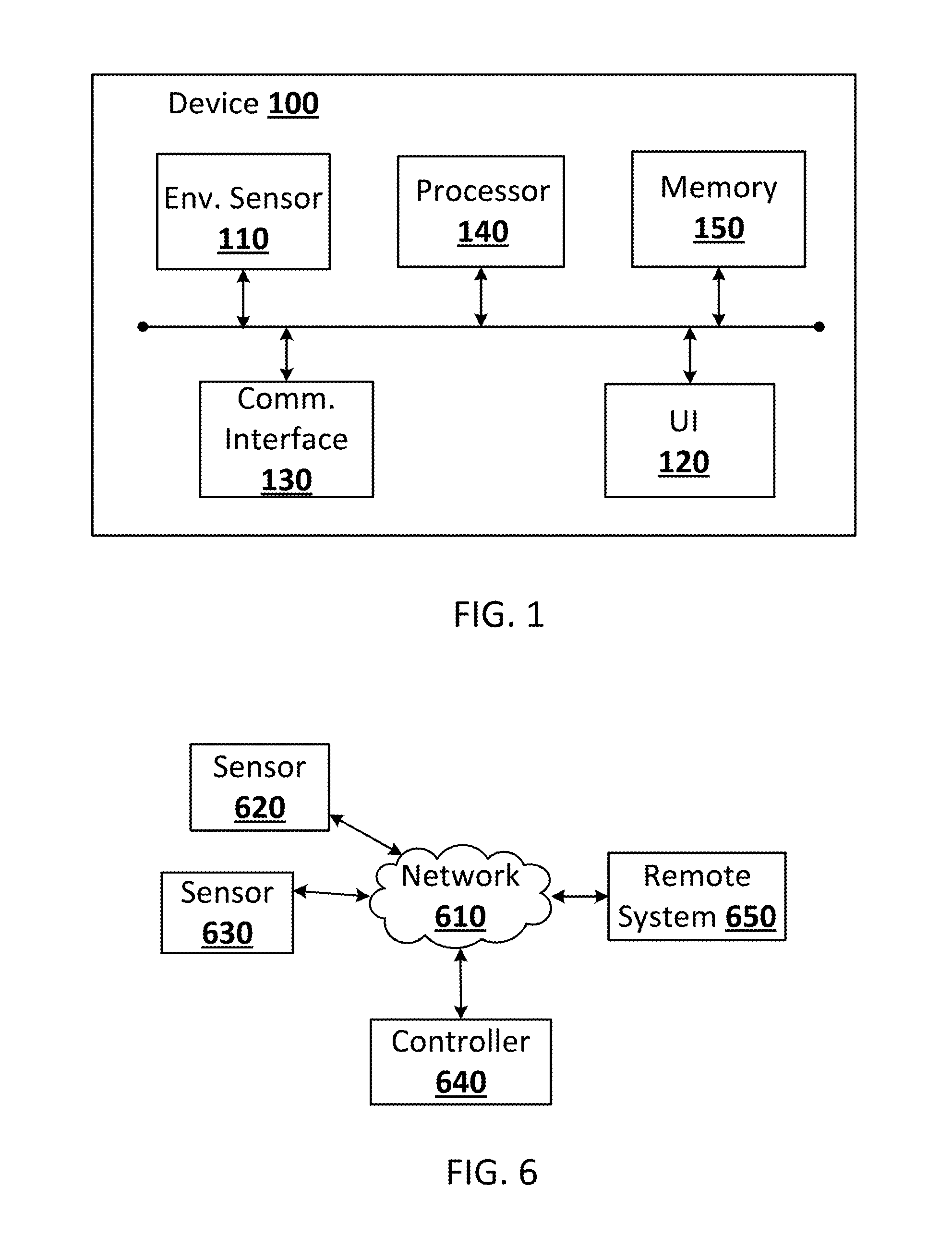
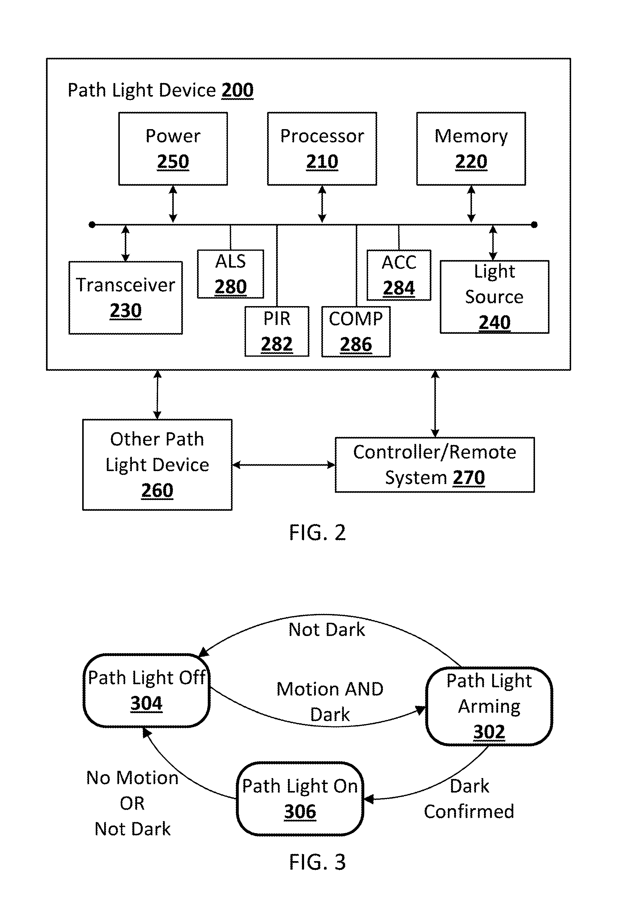
[0019]Implementations of the disclosed subject matter enable automatic system control in which “sleepy” or slow sensor sampling states can be changed to “active” or faster sampling states, or combinations thereof, based on feedback from sensors and other changes in the state of the device to balance user comfort, energy efficiency and proper system function. One implementation of the disclosed subject matter enables automatic path light illumination control that can operate using multiple sampling modes and sampling periods, and where the transition between each mode and / or sampling period is designed to balance user comfort, energy efficiency, sensor position and proper system function. A path light control device is provided that can include a processor and light source, and any combination of ambient light sensors (ALS), passive infrared (PIR) sensors, accelerometers and compass sensors, where the sampling mode and sampling period may be determined to permit the ALS to accurately...


PUM


Abstract

A path light control device that can include a processor and light source, and any combination of ambient light sensors (ALS), passive infrared (PIR) sensors, accelerometers and compass sensors, where the sensor sampling mode and sampling period may be dynamically determined to permit the ALS to accurately measure an ambient light without excessive operation. The accelerometer and compass sensor may be provided to determine device movement and orientation to avoid sensor operation when movement or orientation of the device indicates that the data of the sensor is not applicable for proper device control.

Description

BACKGROUND[0001]A “path light” generally refers to a light source that illuminates a pathway. By comparison, a room light illuminates, for example, an entire room including any included pathways. Path lights provide more targeted illumination and are typically utilized to illuminate a sidewalk or other path on the exterior of a home, or a particular path or hallway on the interior of the home, especially those that may not be properly or efficiently illuminated by room lights. In a commercial setting, such as a movie theater, a path light can be utilized to illuminate stairways, corridors or other paths to direct consumers to their seats or to exits, and can include a variety of lighting sources, controls and sensors, such as ambient light sensors, to ensure that the path light illuminates only in dark conditions.[0002]However, since many of the path light control devices are battery powered, each has to consider how frequently power is used to sample the associated environmental se...

Claims


Application Information

Patent Timeline
Patent Type & Authority Applications(United States)
IPC IPC(8): H05B37/02H05B44/00
CPCH05B37/0218H05B37/0227H05B47/175H05B47/11Y02B20/40H05B47/13H05B47/196H05B47/197
Inventor DONHOWE, KRISTOFFER JOHNMODI, YASHTHOMAS, DOUGLAS JOHNMA, SHAO-PO
Owner GOOGLE LLC
Learn More