Dental Mirror

a technology of dental mirrors and mirrors, applied in the field of dental mirrors, can solve the problems of unsatisfactory and uncomfortable dental postures of dentists, and achieve the effect of convenient processing of dental consultation, treatment or surgical operation

Inactive Publication Date: 2016-12-01
CHEN LEON
View PDF4 Cites 5 Cited by
  • Summary
  • Abstract
  • Description
  • Claims
  • Application Information

AI Technical Summary

Benefits of technology

[0011]It is one objective of this invention to provide a dental tool, which combines a dental mirror and liquid sucking structure, so that when dentist is using the dental mirror, the liquid or fragment in patient's oral cavity can be sucked simultaneously to conveniently process dental consultation, treatment or surgical operations.
[0012]It is another objective of this invention to provide a dental tool for a dentist can operate independently by oneself, so as to reduce tools in oral cavity with convenience and space saving.
[0021]According to one embodiment of the dental mirror, one end of the tube has a connecting element, and the connecting element includes an inserting portion and a blocking portion connected to the inserting portion. The inserting portion is inserted in the handle, and the blocking portion is abutted against an outer edge of the handle. In one further embodiment, the inserting portion has at least one hook formed on a periphery thereof, and an inner of the handle is formed with at least one groove, so that the hook and the groove can be engaged mutually.
[0028]Thus, the present invention has advantages as follows. When the dentist uses the dental mirror of this present invention, liquid or fragment in the patient's oral cavity can be sucked, and does not alternatively use a traditional dental mirror and suction device. Many pauses during therapy process can be avoided, and time of therapy process is saved. Manpower of dental assist is reduced effectively. In addition, the dental mirror of the present invention can be operated by dentist oneself single, and is not occupied the space of the oral cavity, which is used more conveniently.

Problems solved by technology

However, the dentist sometimes needs to work in some postures very uncomfortably.
In addition, numerous dental tools arranged in a narrow oral cavity M will obstruct the dental's checkups, treatment, or surgery, which is not ideal.

Method used


Image

  • Dental Mirror
  • Dental Mirror
  • Dental Mirror

Examples


first embodiment

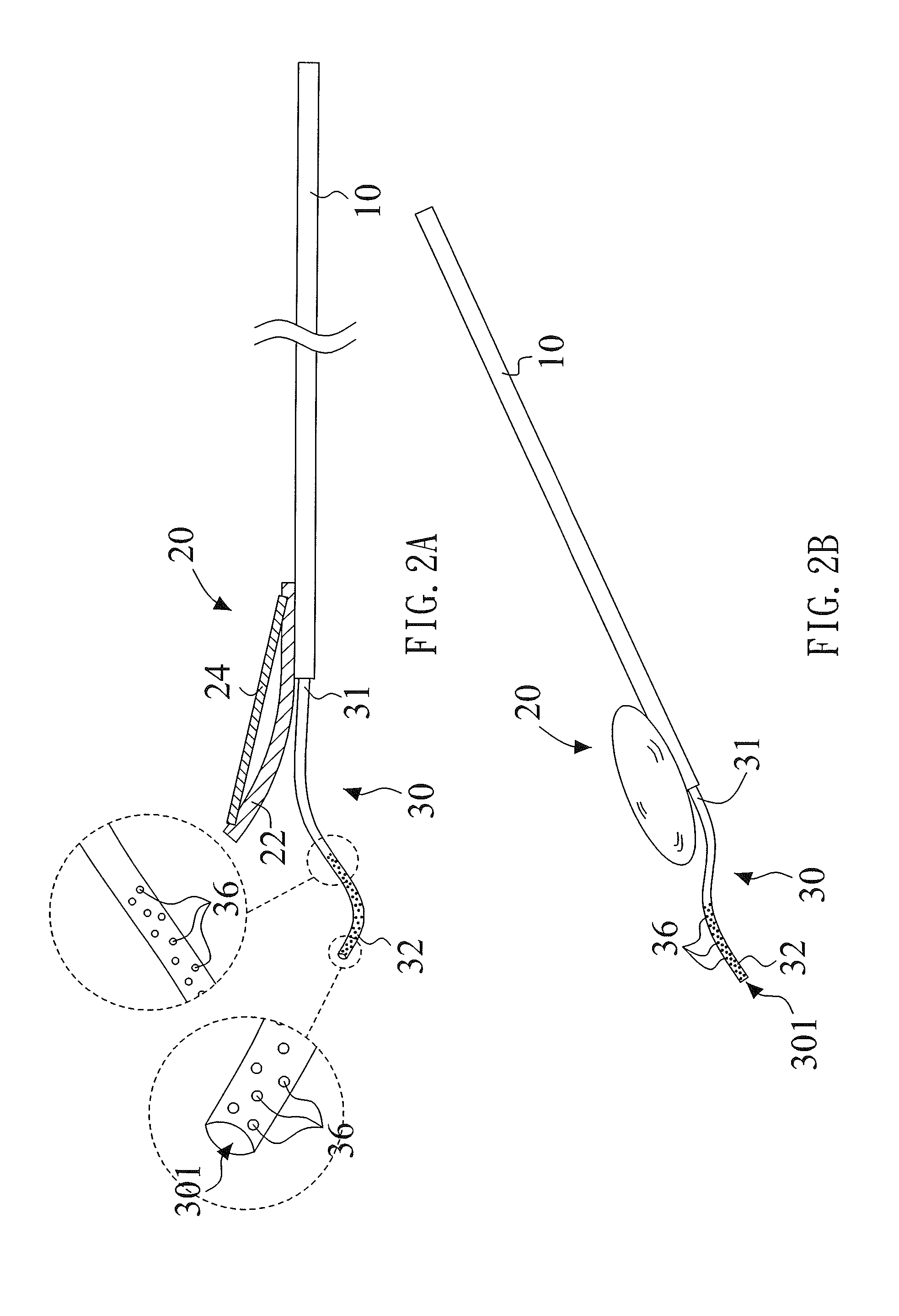
[0051]Please refer to FIGS. 2A and 2B, which is a side view and perspective view of dental mirror of first embodiment of the present invention. The present invention provides a dental mirror, or called mouth mirror, which includes a handle 10, a mirror unit 20 connected to one end of the handle 10 and a tube 30. The handle 10 can be made of metal material, plastic material or other material . . . etc. The mirror unit 20 includes a cover 22, and a glass component 24 disposed on the cover 22. The glass component 24 is detachably engaged with, adhered to or clipped on the cover 22. The tube 30 is connected to the handle 10 and extended to a back of the mirror unit 20. A part of the tube 30 is formed with a plurality of inhaling holes 36 for sucking liquid. In other embodiments, the tube 30 can be arranged on a periphery of the mirror unit 20, and the mirror unit 20 can be disposed at one left end of the tube 30.

[0052]In this embodiment, the handle 10 can be hollow-shaped. The tube 30 i...

second embodiment

[0055]Please refer to FIG. 4, which is a side view of dental mirror of second embodiment according to the present invention. Different from the above embodiment, this embodiment has a plurality of inhaling holes 36, which are formed away from a free end 32 of the tube 30 slightly. For this embodiment, the inhaling holes 36 are distributed on a middle part of the tube 30 which is exposed outside the handle 10, that is, between the fixing end 31 and the free end 32.

third embodiment

[0056]Please refer to FIG. 5, which is a side view of dental mirror of third embodiment according to the present invention. Different from the above embodiment, the inhaling holes 36 of this embodiment are formed away from the free end 32 of the tube 30, and closed to the handle 10, that is closed to fixing end 31 of the tube 30.


PUM


Abstract

A dental mirror includes a handle, a mirror arranged at one end of the handle, and a pipe connected to the handle and extended beyond the mirror. The pipe is partially formed with a plurality of liquid-sucking holes. When dentist uses the dental mirror, it can suck up liquid or debris in oral cavity of the patient.

Description

BACKGROUND OF THE INVENTION[0001]1. Field of the Invention[0002]The present invention is related to a dental mirror. In particular, the present invention relates to a dental mirror intended for use in dental and surgical operations so that a dentist can observe patient's oral cavity or teeth conditions.[0003]2. Description of Related Art[0004]In general, no matter during dental operation or dental examination, the oral cavity of dental patient usually has water, saliva, or cooling liquid (usually is clean water) when drilling teeth. To smooth the dental operation or dental examination, such water, saliva, or cooling liquid all need dental machine or tool to extract out or exhaust, so as to avoid affecting a working vision of dentist or dental assist.[0005]As shown in FIG. 1, a drilling equipment 7 and a dental mirror 8 are usually used during dental treatment, such as caries restoration, scaling, and other treatments for patient's teeth. The drilling equipment 7 can be used to clean...

Claims


Application Information

Patent Timeline
Patent Type & Authority Applications(United States)
IPC IPC(8): A61B1/247A61C17/06
CPCA61C17/043A61B1/247A61B1/00094A61B1/00101A61B1/015A61C17/088A61C17/096A61C17/08
Inventor CHEN, LEONCHEN, NINACHEN, AUDREECHEN, NICKCHEN, ALECCHEN, NASDAQCHA, JENNIFER
Owner CHEN LEON
Why Eureka
Try Eureka