Unlock instant, AI-driven research and patent intelligence for your innovation.

Dripper Gripper

a technology of gripper and gripper body, which is applied in the field of dripper gripper and water line support device, can solve the problems of metal stakes being easy to fail, not working well, damage from pests, etc., and achieves the effect of easy driving into the ground

Inactive Publication Date: 2016-12-01
MCCASLIN GARRY +1
View PDF16 Cites 3 Cited by
  • Summary
  • Abstract
  • Description
  • Claims
  • Application Information

AI Technical Summary

Benefits of technology

The patent describes a device for supporting water pipes in a ground. The device includes stakes that are positioned to divide the horizontal support member into three equal parts. The stakes have a pointed end that can be driven into the ground. The stakes are connected to the bottom side of the horizontal support member. The device also has a textured surface for easy driving and a reinforced rail and interior wall to provide support for the water pipes. The technical effect of this device is to provide a simple and effective way to support water pipes in a ground.

Problems solved by technology

However, the practice of burying the irrigation hoses often leads to damage from pests, such as gophers.
These metal stakes are prone to failure from rust or metal fatigue.
While these known prior art retention devices are a convenient way to retain hose and water lines, they do not work very well with certain gauge / capacity water lines because when large volumes of water flow through hoses, it exerts a force on the single stake retention device that may dislodge the hose from the device and / or remove the stake from the ground.
These devices, however, do not allow for multiple hose and water lines to be individually secured within a plurality of retention mechanisms on the same device.
Therefore, where there is a need to use multiple water lines, such as in a commercial orchard, the prior art retention devices lack the ability to retain multiple lines within the same device.
An additional shortcoming of the prior art is the relative location of the retention mechanism on the prior art devices, which are not in an optimal location for retaining, securing, and changing a water line held therein.

Method used


Image

  • Dripper Gripper
  • Dripper Gripper
  • Dripper Gripper

Examples


Embodiment Construction

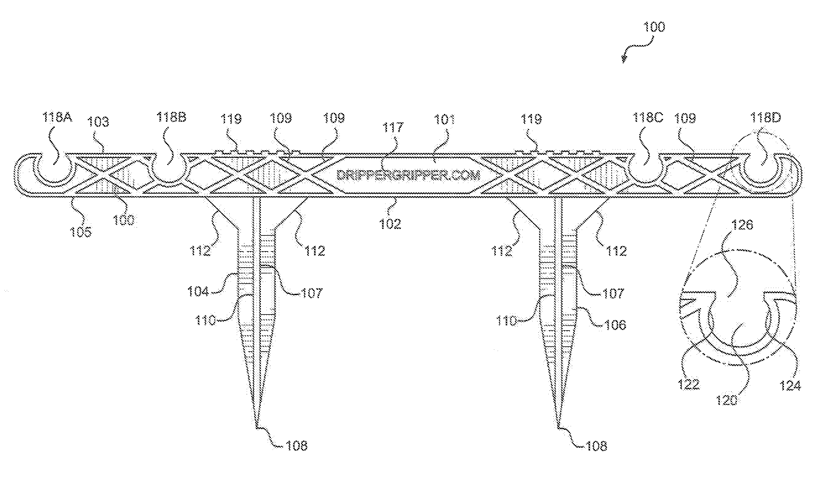
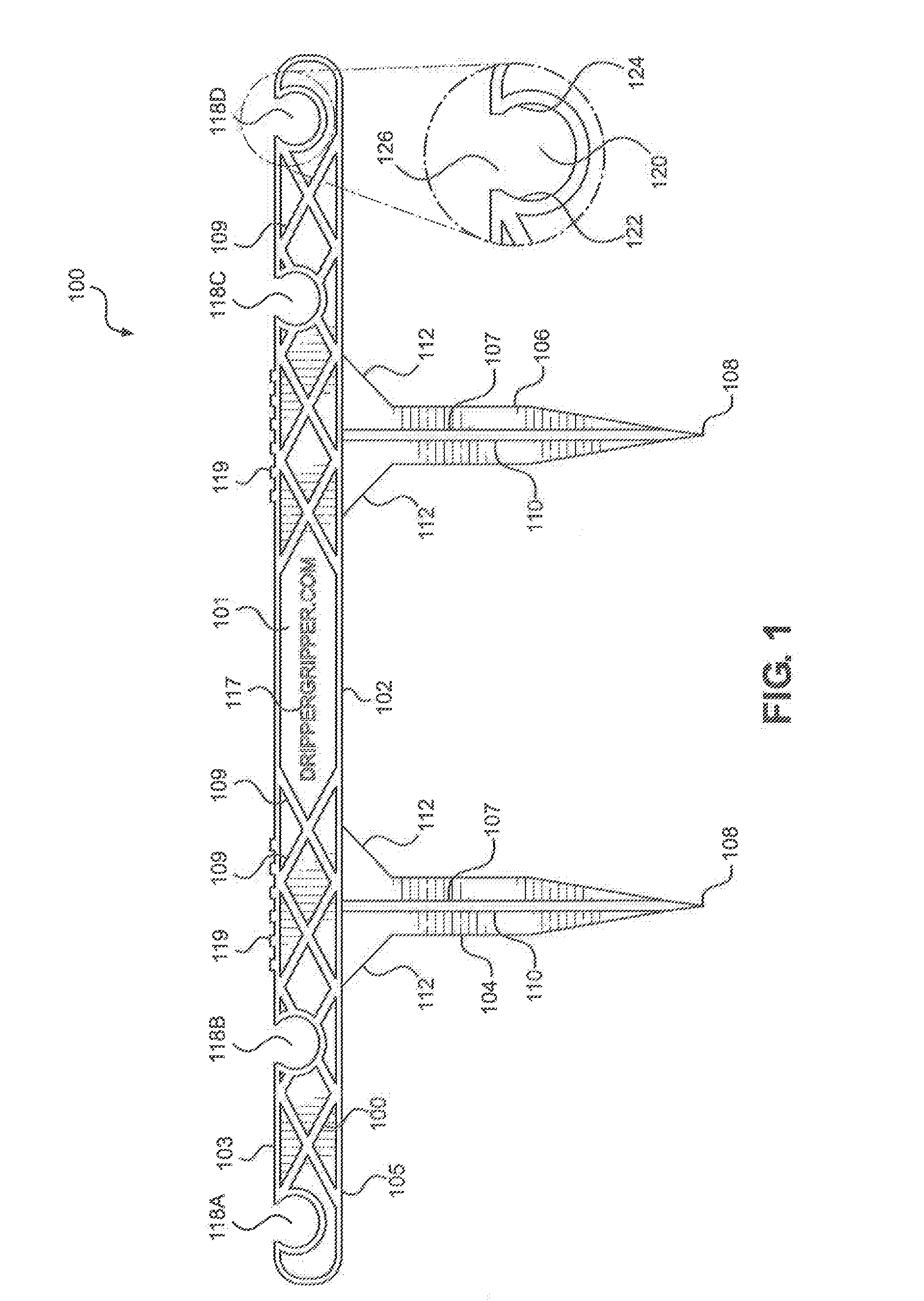
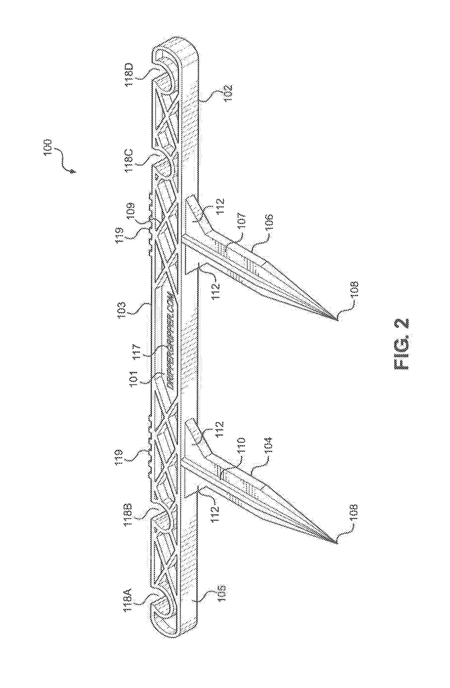
[0025]Referring now to FIG. 1 and FIG. 2, there is shown a front view and lower perspective view of the hose and water line support device 100. The hose and water line support device 100 comprises a horizontal support member 102 having a top side 103 and a bottom side 105 connected on opposite sides of a middle support 101 such that the top side 103, middle support 101 and bottom side 105 form a typical I-beam configuration. A first stake 104 and a second stake 106 each extend perpendicularly downward from the bottom side 105 of horizontal support member 102. In an embodiment, first stake 104 and second stake 106 are positioned with respect to one another so as to trifurcate the horizontal support member 102 into three equal portions; a first third portion, a middle third portion and a final third portion. Overall, the device is shaped like the Greek letter “π” (Pi). Middle support surface 101 is shown braced with diagonal supports 109. Diagonal supports 109 also support the top sid...


PUM


Abstract

A water line support device includes a pair of stakes that extend perpendicularly downward from a horizontal support member and a plurality of water line retention mechanisms that may be positioned on the top or bottom side of the horizontal member. In simple form, the plurality of integral retention mechanisms have a recessed channel that is oriented parallel to the ground and perpendicular to the horizontal member. The horizontal member has a top side and a bottom side connected on opposite sides of a middle support such that the top side, middle support and bottom side form an I-beam configuration when viewed as a cross section of the horizontal member. The middle support can be reinforced or braced with diagonal supports that also are connected to and support the top side and the bottom side of the horizontal member. A logo can be added to the horizontal support member.

Description

RELATED APPLICATIONS[0001]This application is a conversion of, and claims the benefit of priority to, the United States Provisional Patent Application for “Dripper Gripper,” Ser. No. 62 / 168,409, filed on May 29, 2015, and currently co-pending, and also is a conversion of, and claims the benefit of priority to, the United States Provisional Patent Application for “Dripper Gripper,” Ser. No. 62 / 292,780, filed on Feb. 8, 2016, and currently co-pending. Both applications are incorporated fully herein by this reference.FIELD OF INVENTION[0002]The present invention relates to an agricultural support device and system. More particularly, the present invention pertains to a water line support device that is driven into the ground. The invention may securely retain water lines along the ground in an orderly fashion and resist unwanted rotation and tangling of water lines. Additionally, the water line support device has a plurality of water line retention mechanisms for retaining individual w...

Claims


Application Information

Patent Timeline
IPC IPC(8): B05B15/06A01G25/02
CPCA01G25/02B05B15/062A01G25/00A01G25/023B05B15/622
Inventor MCCASLIN, GARRYMCCASLIN, DUSTIN
Owner MCCASLIN GARRY