Iron-type golf club head
a golf club and iron-type technology, applied in golf clubs, golf, sport apparatus, etc., can solve the problems of difficulty for the average golfer to hit a ball at such a suitable position, and achieve the effect of improving the flying distance and the directionality of the ball hit, reducing the height of the sweet spot, and increasing the inertia momen
Active Publication Date: 2016-12-08
SUMITOMO RUBBER IND LTD
View PDF59 Cites 2 Cited by
- Summary
- Abstract
- Description
- Claims
- Application Information
AI Technical Summary
Benefits of technology
The present invention provides an iron-type golf club head that can improve the flying distance and directionality of a ball hit by an average golfer. This is achieved by satisfying conditions that increase the moment of inertia and lower the sweet spot height, which results in a more powerful impact and better ball flight.
Problems solved by technology
However, it is difficult For the average golfers to hit a ball at such a suitable position every time.
Method used
View moreImage
Smart ImageViewing Examples
Examples
working example 1
FIG. 5
[0126]weight members' materials: tungsten-nickel-iron alloys
toe-side weight member's specific gravity: 16
heel-side weight member's specific gravity: 14
sole cover's specific gravity: 9.5
face plate's material: titanium alloy (specific gravity: 4.4)
face plate receiving frame's material: SuS630[0127]specific gravity: 7.8
Login to View More PUM
 Abstract
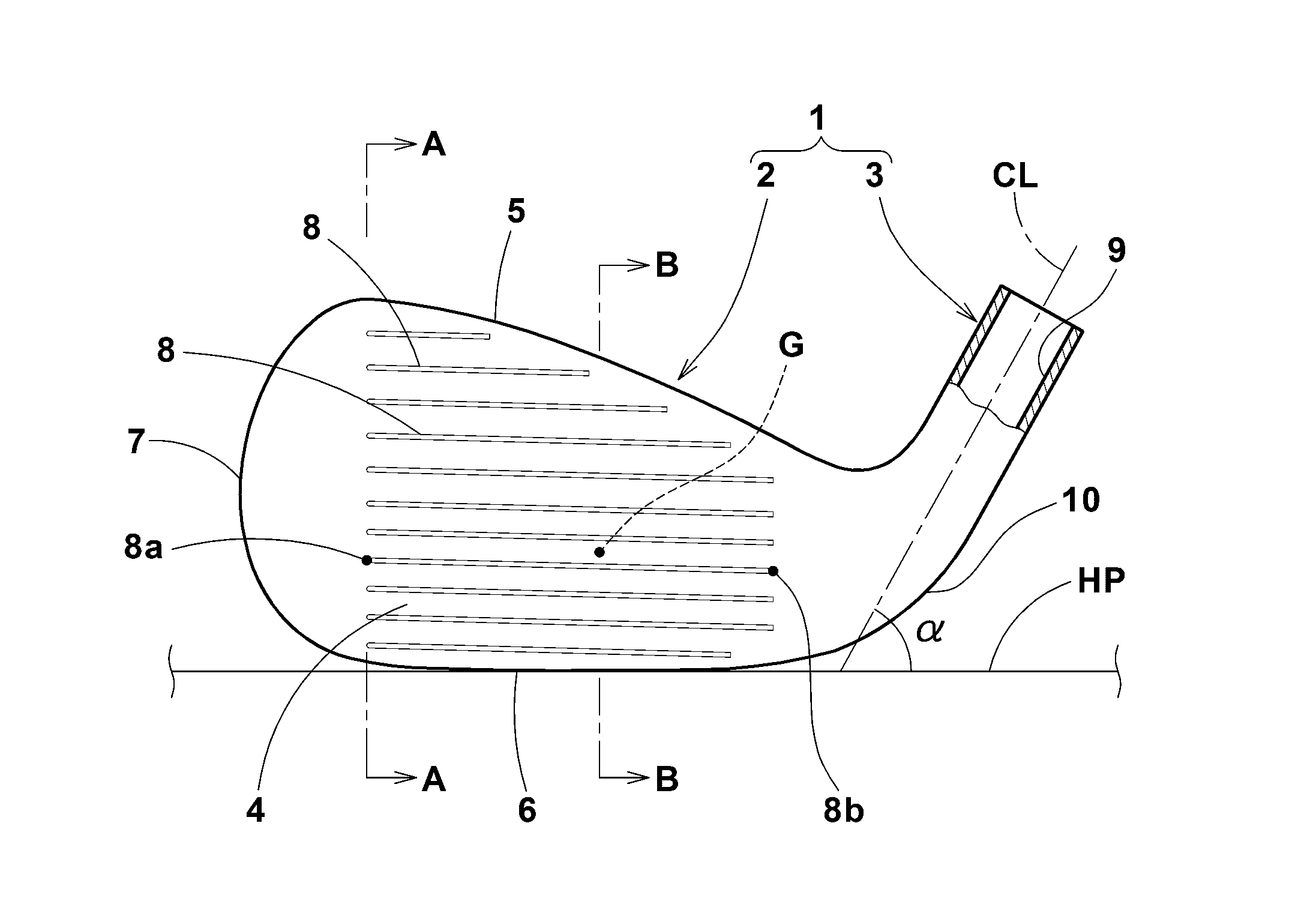
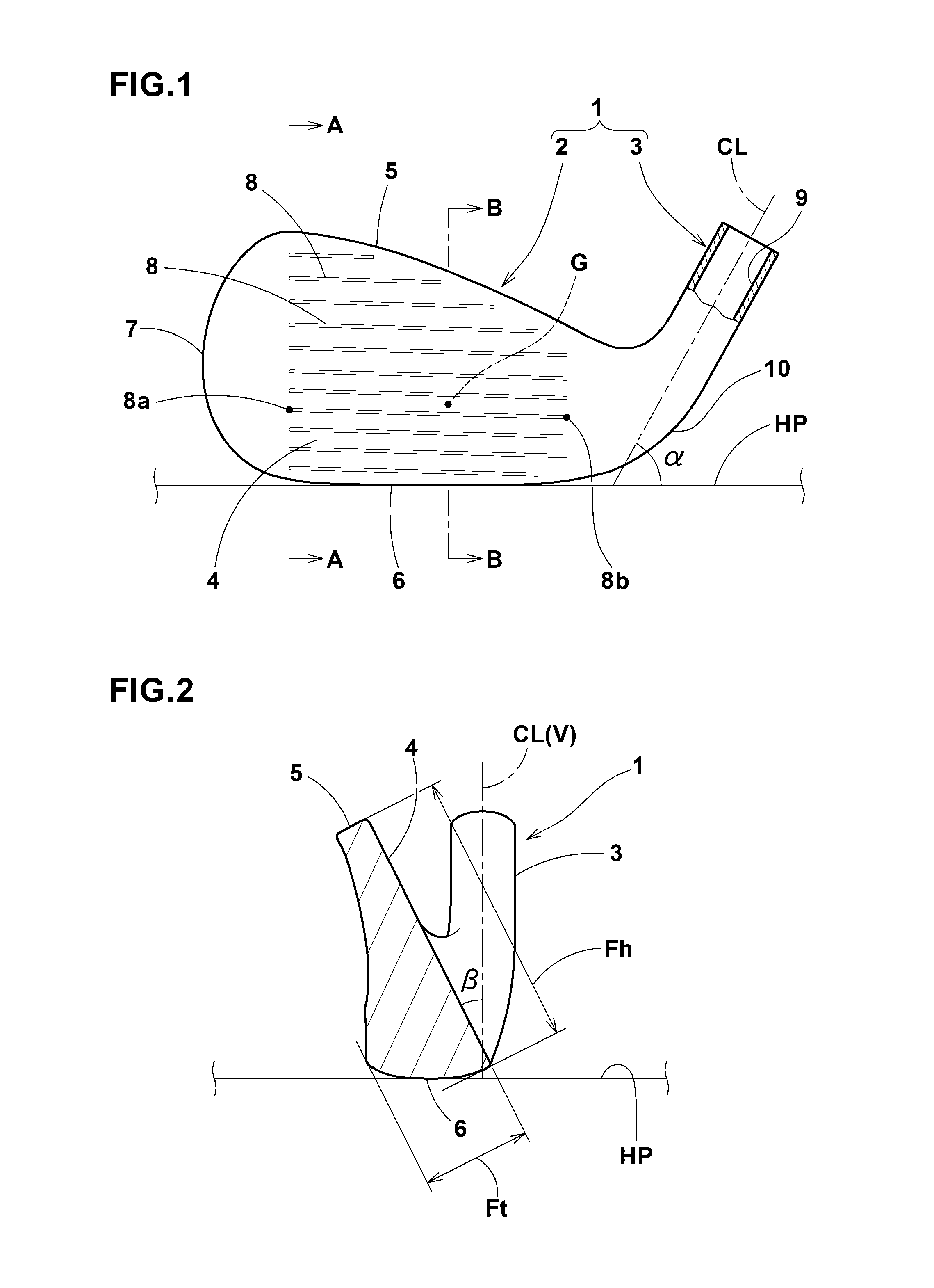
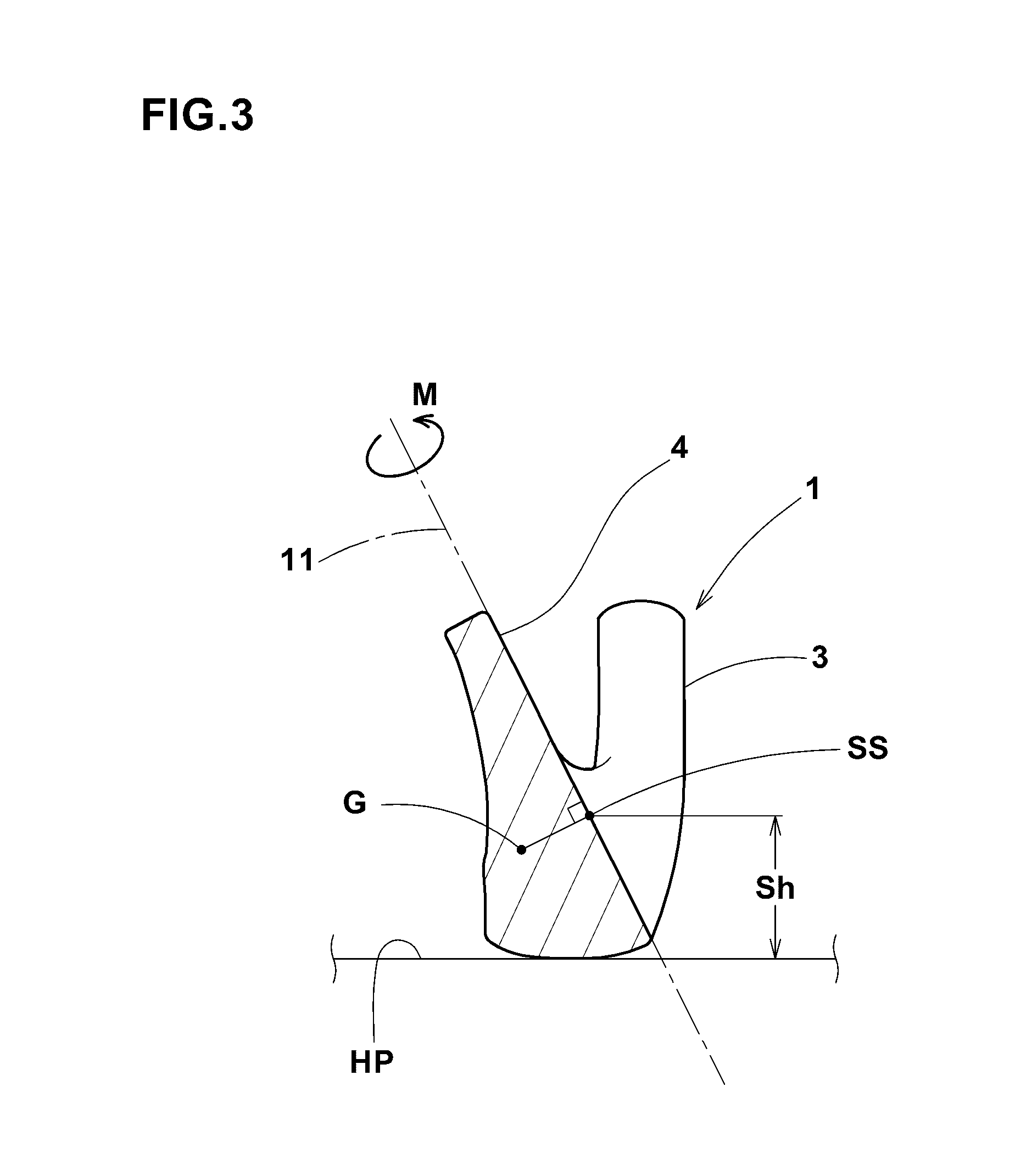
An iron-type golf club head having a club face provide with a plurality of grooves extending in the toe-heel direction, satisfies the following conditions (1) the loft angle of the club head is not more than 41 degrees, (2) the thickness of the club head is not more than 23 mm, (3) the height of the club face measured along the club face at the position of the most toe-side end of the grooves is not less than 53 mm, (4) in a standard state of the club head set on a horizontal plane at the lie angle and loft angle specified for the club head, the ratio M / Sh (g sq·cm / mm) of a moment M of inertia (g sq·cm) around a first axis passing through a sweet spot in parallel with the club face and perpendicularly to the grooves, and a sweet spot height Sh (mm) which is the vertical height from the horizontal plane to the sweet spot is not less than 152.
Description
BACKGROUND OF THE INVENTION[0001]The present invention relates to a golf club head, more particularly to an iron-type golf club head capable of improving the flying distance and directionality of a ball hit by an average golfer.[0002]In general, an iron-type golf club head is designed such that, when a ball is hit at a suitable position such as the sweet spot or the center of the club face, the flying distance of the ball becomes maximum. However, it is difficult For the average golfers to hit a ball at such a suitable position every time. Therefore, in the case of the average golfers, there is a tendency that the flying distance varies wide.[0003]In the circumstances described above, for example, in the Japanese Patent Application Publication Nos. H9-253248 and H10-295861, an iron-type golf club head in which the position of the center of gravity of the club head is lowered has been proposed. Such a club head accordingly has the sweet spot at a lower position on the club face.[0004...
Claims
Login to View More Application Information
Patent Timeline
 Patent Type & Authority Applications(United States)
IPC IPC(8): A63B53/04
CPCA63B2053/0408A63B53/047A63B2053/0491A63B53/0408A63B53/0433
Inventor NORIMURA, TAKAHIRO
Owner SUMITOMO RUBBER IND LTD
Features
- R&D
- Intellectual Property
- Life Sciences
- Materials
- Tech Scout
- Unparalleled Data Quality
- Higher Quality Content
- 60% Fewer Hallucinations
Learn More Browse by: Latest US Patents, China's latest patents, Technical Efficacy Thesaurus, Application Domain, Technology Topic, Popular Technical Reports.
© 2025 PatSnap. All rights reserved.Legal|Privacy policy|Modern Slavery Act Transparency Statement|Sitemap|About US| Contact US: help@patsnap.com


