
Rigid pavement construction on steel deck and construction method thereof

A construction method and steel bridge deck technology, which can be applied to cohesive pavement paved on site, bridges, bridge parts, etc., can solve the problems of threatening driving safety and easy loosening of gravel, so as to achieve good integrity and improve driving safety , Improve the effect of bending resistance

Inactive Publication Date: 2013-10-30
SOUTH CHINA UNIV OF TECH
View PDF9 Cites 1 Cited by
  • Summary
  • Abstract
  • Description
  • Claims
  • Application Information

AI Technical Summary

Problems solved by technology

The disadvantage of this patented technology is: under the combined action of rainwater and vehicle load, the gravel scattered on the surface of the flexible packing is easy to loose. For high-speed vehicles, the scattered gravel is splashed by the wheels, which seriously threatens driving safety.

Method used


Image

  • Rigid pavement construction on steel deck and construction method thereof

Examples


Embodiment 1

[0021] (1) Pavement structure and materials

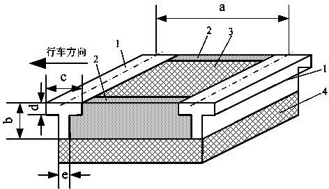
[0022] Such as figure 1 , the components of the pavement structure include: a grid piece formed by a steel grid laid on the bridge deck steel plate 4 and a rigid filler 3 filling the internal gap of the steel grid. The upper surface of the steel grid is flush with the upper surface of the rigid packing, and jointly bear the driving load.

[0023] Among them, the steel mesh is a regular quadrilateral. The grid side length a is 100 mm. The grid height b is the thickness of the pavement layer, which is 25mm. The raw material of the steel grid is Q345qC grade steel specified in GB / T714-2008 "Structural Steel for Bridges". The cross-section of the beam 1 perpendicular to the driving direction is T-shaped; the width e of the lower surface is 10mm; the width c of the upper surface is 1.5 times of the width of the lower surface. The section of the longitudinal beam parallel to the driving direction is rectangular, and the section w...

Embodiment 2

[0033] (1) Pavement structure and materials

[0034] The components of the pavement structure include: a grid piece formed by a steel grid laid on the bridge deck steel plate 4 and a rigid filler 3 filling the internal gap of the steel grid. The upper surface of the steel grid is flush with the upper surface of the rigid packing, and jointly bear the driving load.

[0035] Among them, the steel mesh is a regular quadrilateral. The grid side length a is 1000mm. The grid height b is the thickness of the pavement layer, which is 50mm. The raw material of the steel grid is Q345qC grade steel specified in GB / T714-2008 "Structural Steel for Bridges". The cross-section of the beam 1 perpendicular to the driving direction is T-shaped; the width e of the lower surface is 20 mm; the width c of the upper surface is twice the width of the lower surface. The section of the longitudinal beam parallel to the driving direction is rectangular, and the section width is 20mm.

[0036] The...


PUM


Abstract

The invention provides a rigid pavement construction on a steel deck and a construction method thereof. The rigid pavement construction comprises mesh sheets and rigid filler. The mesh sheets are paved on deck steel plates and are formed by steel meshes. The rigid filler is used for filling gaps inside the steel meshes. The upper surface of the steel meshes is flush with that of the rigid filler. The construction method includes processing sheets of steel meshes; fixing the steel meshes on the deck steel plates through welding; welding all bottom edges of the steel meshes on the deck steel plates; performing shot blasting on the deck steel plates and the steel meshes; coating waterproofing material on contacting faces of the steel meshes and the deck steel plates and the rigid filler; and paving cement concrete with steel fibers added in. By the aid of the rigid pavement construction and the construction method, using security of a pavement layer can be improved, and entire rigidity of the pavement layer can be further improved.

Description

technical field [0001] The invention relates to a road engineering structure and a construction method thereof, in particular to a pavement structure paved on a steel bridge surface and a pavement method thereof. Background technique [0002] The submitted invention patent application "a steel bridge deck pavement structure and its pavement method" (application number: 201310049568.8) provides a new type of pavement structure. Its components include: grid sheets formed by steel grids laid on the bridge deck steel plates and flexible fillers to fill the internal gaps of the steel grids. The steel grid and the flexible filler jointly bear the traffic load. The flexible filler adopts the hot-melt asphalt material with crushed stones scattered on the surface. The disadvantage of this patented technology is: under the combined action of rainwater and vehicle load, the gravel scattered on the surface of the flexible packing is easy to loosen. For high-speed vehicles, the scatter...

Claims


Application Information

Patent Timeline
Patent Type & Authority Applications(China)
IPC IPC(8): E01D19/12E01D21/00E01C7/14
Inventor 葛折圣
Owner SOUTH CHINA UNIV OF TECH
Learn More